Page Contents
Signal Processors
An important step in optimizing a system involves signal processing. MAPP 3D enables designers to add and configure signal processors in the design phase, view prediction results, and export processor settings directly to real hardware. The output processing functions of all Galileo GALAXY processor models are available in MAPP 3D.
NOTE: MAPP 3D processors include Delay Integration. The current version of Compass/GALAXY includes Product Integration, which combines Delay Integration and an option to recall Starting Point EQ files. These Starting Point files can be recalled in Compass and pushed to MAPP 3D when real or virtual processors are synchronized with MAPP 3D for modeling and evaluation.
Processor Settings Tab and Galileo GALAXY Models
By default, one GALAXY 816 processor is added to the MAPP 3D Project when an empty project is opened.
Add/Edit Signal Processor
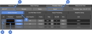
To add/edit a signal processor, perform these steps (see figure below):
- INSERT > SIGNAL PROCESSOR to add a processor, select model, enter unique name
- select Processor Settings tab
- select a processor from the drop-down

- select Device Overview tab

- click any processing icon
 or select the Output Processing tab to view and modify settings
 - right-click a channel number
 to open the copy/paste dialog
 - right-click a processing icon to open the copy/paste dialog
- EXPORT button
 creates a PDF patch sheet listing output channel number and name, and connected loudspeaker(s)
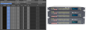
Processor Settings Tab – Device Overview Tab
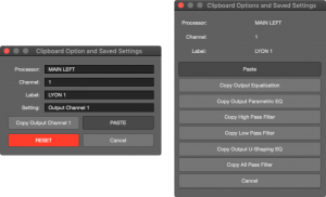
Channel and Processing Copy/Paste Windows
Remove Signal Processor
To remove a signal processor from a project, select the Processor Settings tab, select a processor from the drop-down menu, and click the DELETE button at the top of the tab. Loudspeakers assigned to a deleted processor are no longer assigned to a processor and output channel.
To assign loudspeakers or arrays to a remaining processor and channel, select a loudspeaker or an array in Model View, then select the Object Settings tab. Make new processor and output channel selections using the drop-down menus.
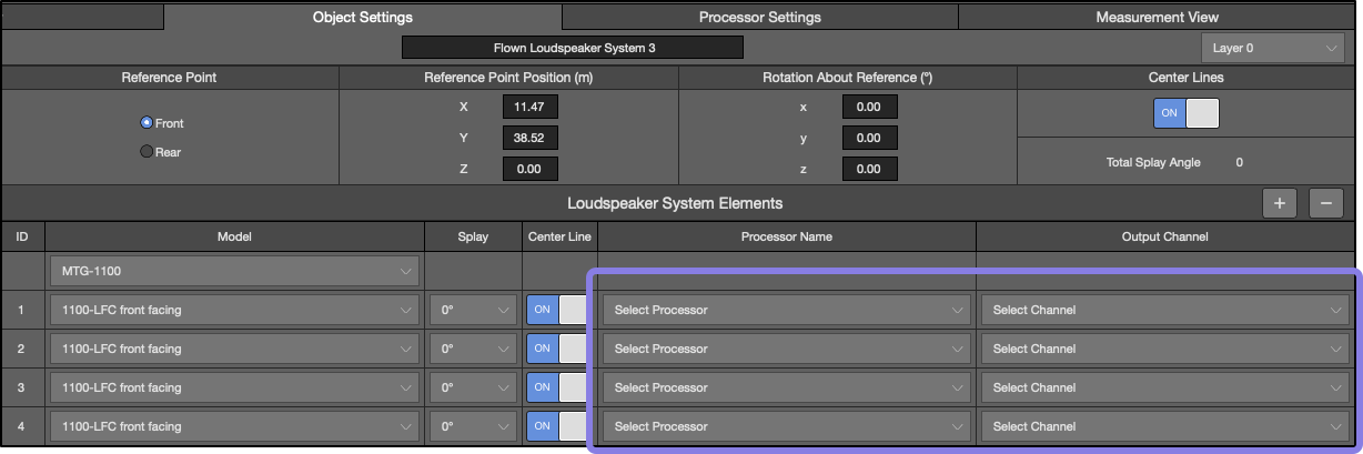
Object Settings, Loudspeaker Array – Processor and Output Channels Not Assigned
Output Processing Tab
The Output Processing tab provides access to all processor settings (see figure below).
- select Device Overview, LMBC, Output Processing, or Snapshot Library tabs

- output channel selection
- combined filter phase response
- combined filter magnitude response
- processor settings tabs
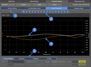
Processor Settings Tab – Output Processing
Channel Settings
Settings for basic functions, enable/bypassing processing, high/low-pass filters, polarity, gain, and mute are accessed via this tab.
Correction for high frequency air absorption over distance is enabled here. When enabled, enter the distance between the loudspeaker and audience area. Based on environmental settings entered in Project Settings and distance, compensation filters are automatically added. When used, adjust the temperature and humidity setting when there is a change of 3 ºC or 5% humidity. Atmos. Gain Factor will increase/decrease the magnitude of these filters. The higher the percentage value, the more gain the filters can add, and the larger the cost in headroom. Select Atmos Corr. Response in FILE > PROJECT SETTINGS > PROCESSOR tab to view the correction filter response in the output processing plotter.
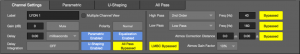
Processor Settings – Channel Settings
Parametric
Each channel has ten bands of parametric equalization. Filter values can be manually entered below the plotter window. Click-drag a filter in the plotter to change the gain. After a filter has been selected, click-drag the blue bars to adjust the bandwidth.
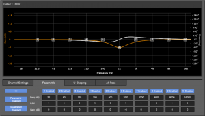
Processor Settings – Parametric Equalizer
U-Shaping
Meyer Sound’s proprietary U-Shaping equalization filters are adjusted with these controls. Values can be manually entered or click-drag the horizontal and vertical bars in the plot to change the settings.
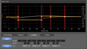
Processor Settings – U-Shaping Filters
All Pass
All Pass filters affect phase response, not magnitude response. These filters should only be used for a specific reason, e.g., adjusting the phase response of one loudspeaker to match another model.
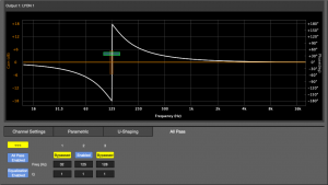
Processor Settings – All Pass Filters
Snapshot Library Tab
coming soon… Just like Compass control software, processor Snapshots can be saved and recalled. By default each signal processor includes one snapshot, named Factory Defaults.
- double-click a Snapshot name to edit the name
- click CREATE NEW to capture all of the processor settings and save them as a Snapshot in the application
- click SAVE OUTPUT CHANNELS to save the settings of the processor outputs as a file on a storage device (hard drive, etc.)
- click UPDATE to overwrite the currently selected Snapshot with the current processor settings
- click RECALL to overwrite the settings of the processor with those of the selected Snapshot
Low-Mid Beam Control Tab
LMBC is used to alter the low-frequency directivity of LEO series models to better match the high-frequency coverage in some cases. See the Real World Low-Mid Beam Control video. Using MAPP 3D to model the result of using LMBC is the first step of analysis. Place microphones on-axis of an array at the beginning, middle, and end of coverage; use more for larger arrays. Store traces with and without LMBC and compare results. Are the traces more similar with LMBC enabled, or not? Use the method that provides the most uniform spectral tilt.
For each array, some minimum requirements must be met to use LMBC:
- each array element is driven from a Galileo GALAXY output, one element per output1
- array minimum length must be exceeded
- the angle between the top center line and the bottom center line cannot exceed limits
Constraints are built in and an error displayed in the Outputs column (x below) if the entered values exceed established limits that would negatively affect directivity.
- Control Type: Beam Spread or Steer, make selection based on design goals and coverage needs
- Elements per Output: number of array elements (loudspeakers) connected to a single processor output
- Start on Output: the processor output channel number connected to the element at the top of the array2
- No. of Elements: total number of elements in one array
- Element Location:
- for arrays driven by one processor or the first processor driving an array that uses outputs from multiple processors, select 1
- for a second processor driving the same array, select the number of processor outputs of the first processor driving the array, plus one
- Product Type: select model of array elements3
- Array Splay: angle between the center lines of the top and bottom elements of an array, available in Object Settings tab, see below image
- Associated Outputs:
- when enabled and valid parameters selected, displays output channels LMBC is applied to and the average All Pass filter setting4
- if parameters are out of limits, an error is displayed
NOTES:
1 If an array is long enough, two array elements per processor output is allowed. An error will be displayed if an array is too short.
2 Subsequent processor output channels are connected to corresponding array elements in order, starting at the top of the array.
3 LMBC is not available for mixed-model arrays.
4 Set All Pass filters on processor outputs connected to loudspeakers in close proximity to the array using LMBC with these parameters.
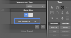
Object Settings – Loudspeaker Array Selected, Total Splay
What’s Next?
Please see Add Loudspeakers next.