Page Contents
Add Loudspeakers
Add loudspeakers to a project to optimize location and determine the appropriate loudspeaker type and model. Several types of loudspeaker systems and individual loudspeakers are available to be added to a project. Six different types of arrays and individual loudspeakers are available.
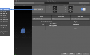
Insert Loudspeaker – Type Selection
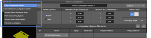
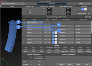
Insert Loudspeaker
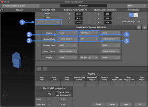
To insert a loudspeaker, perform these steps (see figure below):
- select INSERT > LOUDSPEAKER SYSTEM or right-click in the model space and select INSERT LOUDSPEAKER SYSTEM
- select loudspeaker type from drop-down

- enter unique name

- select layer

- enter location coordinates and rotation
 and
and 
- make other selections based on loudspeaker type
Common Properties and Preferences
Insert Loudspeaker – Flown Loudspeaker System
NOTE: 1 Some array configurations are not physically possible in practice.
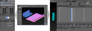
Edit Loudspeakers
Loudspeaker and array properties are edited in two places: Express Settings and Object Settings.
Reposition Loudspeaker(s)
Loudspeakers and arrays can be moved within the boundary limits of the model using two methods:
- select loudspeaker or array in the model
- click-drag the reference point (yellow sphere) to a new location
or
- select loudspeaker or array in the model
- use Express Settings pane or Object Settings tab, enter new values or select a value (double-click) and use the up/down arrow keys
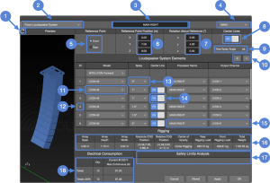
Express Settings
The basic parameters of an array or a loudspeaker are viewed and edited in the Express Settings pane. Use the Express Settings drop-down to select the desired object. Changes are viewed in the Model View immediately. This is helpful when changing splay angles between elements of an array, for example.
Object Settings
All of the parameters of an array or a loudspeaker are viewed and edited in the Object Settings tab. Select the loudspeaker or array in Model View. Select Object Settings tab to edit parameters. Changes are viewed in the Model View immediately. Double-click tab label to un-dock, top bar of window to dock again.
NOTE: Zoom, pan, and orbit are available in preview pane of Object Settings tab (right below).
Express Settings – Flown Loudspeaker Array, Model View Tab, Object Settings – Loudspeaker System
View Menu
The View menu drop-down offers several helpful visual markers related to loudspeakers and arrays that are toggled on/off. Please see View Menu.
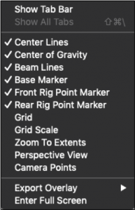
View Menu – Loudspeaker Selections
Loudspeaker Type Details
Each array type has some properties and preferences that are unique and which are listed below.
Flown Loudspeaker System
Flown Loudspeakers Systems are line array systems, including full-range models, subwoofers, or both (notes refer to the figure below).
First Array Element:
Rigging grid selection ![]() . Grids that can be rotated to change where the center of gravity of the loudspeaker array intersects the grid; will have a Forward and Rearward option. Forward is marked as Maximum Uptilt on the grid label and Rearward is marked as Maximum Downtilt.
. Grids that can be rotated to change where the center of gravity of the loudspeaker array intersects the grid; will have a Forward and Rearward option. Forward is marked as Maximum Uptilt on the grid label and Rearward is marked as Maximum Downtilt.
Once the array grid angle and array element splays are optimized for coverage, note the front and rear rigging loads. Select the opposite grid orientation and note the rigging loads again. Compare the results and use the grid orientation that most evenly spreads the load between front and rear rigging points.
Second Array Element:
The loudspeaker model options of this drop-down are constrained by the grid selection ![]() .
.
Splay Angles:
The first angle is the splay between the grid and the top loudspeaker ![]() . For models that have splay options at this connection point, the available hardware angles are listed in the drop-down. The subsequent angles are between each element and the element above it
. For models that have splay options at this connection point, the available hardware angles are listed in the drop-down. The subsequent angles are between each element and the element above it ![]() . In the example below, the splay between ID2 and ID1 is 1.0 degree, between ID3 and ID2 1.5 degrees.
. In the example below, the splay between ID2 and ID1 is 1.0 degree, between ID3 and ID2 1.5 degrees.
Insert Loudspeaker – Flown Loudspeaker System
Auto-Splay
For Flown Loudspeaker Systems, Auto Splay calculates the angles between elements of an array for best coverage, depending on the number of elements selected for a prediction plane. Adjust splay angles to satisfy design goals.
Auto-Splay requires at least one flown or ground stacked loudspeaker array and one geometry. When viewed from above, the center lines of the array need to intersect the geometry before Auto-Splay is functional. In some instances, when using auto-splay with multiple geometries that overlap in the X/Y plane, additional editing of the splay angles may be required.
To Auto-Splay, perform these steps (see figure below):
- TOOLS > AUTO-SPLAY
- select loudspeaker system

- select prediction plane(s)
- select Assigned Elements (number of array elements allotted to each prediction plane); can be zero, see note below
- select Aiming Factor (how many array elements are aimed above end of prediction plane)
- select Smallest and Largest Splay Limits

NOTE: Elements Linear Coverage is the average distance between center lines of the array ![]() . This represents the coverage density for the prediction plane. For multiple prediction planes, adjust the number of elements selected for each prediction plane to most closely match the Elements Linear Coverage values.
. This represents the coverage density for the prediction plane. For multiple prediction planes, adjust the number of elements selected for each prediction plane to most closely match the Elements Linear Coverage values.
The Prediction Plane table lists the prediction planes that are on-axis of the array elements.
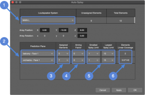
Auto Splay Window

Model View – Before and After Auto Splay
Ground-Stacked Loudspeaker Systems
The loudspeaker model drop-down list is constrained to those models that are suitable to ground stack.
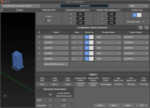
Insert Loudspeaker – Ground Stacked Loudspeaker System
Gradient Flown Subwoofer Array
Gradient subwoofer arrays have some elements facing forward (front) and others facing rearward (rear), in addition to signal processing, to create a cardioid coverage pattern. Additional features of this dialog (refer to figure below):
- Array elements are identified as Front or Rear to indicate the physical orientation .
- Array polarity reverse, maintains the polarity difference between front and rear elements .
- Elements are not individually added or removed. The quantities available optimize the array directivity.
- Front and rear elements are routed to different processor outputs because the polarity is opposite between front-facing and rear-facing elements .
- The Steering Delay selection automatically adds additional delay time to the processor output assigned to the rear-facing elements, which is different for each model .
NOTE: The Steering Delay time in MAPP 3D is different than the delay time used when the array is deployed. The datasets in MAPP 3D do not include the distance/time for sound to travel around the loudspeaker enclosure. The deployment delay time will be longer.
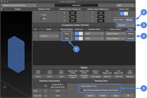
Insert Loudspeaker – Gradient Flown Subwoofer Array
Point Source Array System
Available Point Source Array Systems models are constrained to full-range, point-source models that can be arranged in clusters with Meyer Sound provided hardware. Available splay angles between elements are supported by Meyer hardware.
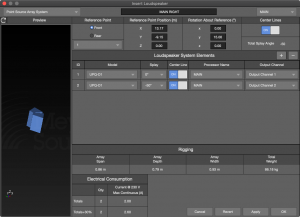
Insert Loudspeaker – Point Source Array System
N-Point Source Array System
Used to build arrays, including the rigging options. These are currently constrained to only horizontal arrays. (coming soon, vertical rows)
Insert Loudspeaker – N-Point Source Array System
Individual Loudspeaker
Select this loudspeaker type to insert an individual loudspeaker. The Reference Point is selectable from the drop-down. CRDM (Center of Rotation During Measurement) is the point inside a loudspeaker that was the point of rotation when the loudspeaker data was recorded in our anachoic chamber.
Insert Loudspeaker – Individual Loudspeaker
CAL Loudspeaker System
(in development…)
What’s Next?
Please see Pressure Plots next.