Page Contents
Start a MAPP 3D Project
Templates
Templates are selected from the Welcome Window or application menu. Click TEMPLATES, select template file, then click CHOOSE. When the Welcome Window is closed, use the FILE > OPEN TEMPLATE menu to open templates.
Templates are provided as examples to easily explore the functions of MAPP 3D. We anticipate adding additional templates to satisfy user requests and needs.
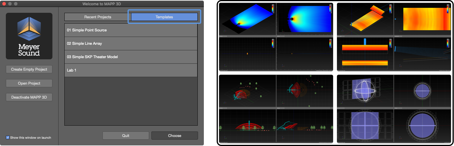
Welcome Window, Select Template and Template File Images
System Design Project Workflow
MAPP 3D can be used in a variety of ways. When starting a system design, these are the steps usually taken:
- gather preliminary project information
- create new project
- enter project properties
- save new project
- make application preference choices
- import drawing(s)
- create additional layers
- add geometry
- add processors
- add loudspeakers
- add microphones
- check and optimize performance
- save project
- export screenshots and reports
- push settings to processors
Project, Start to Finish
After the MAPP 3D application is installed and loudspeaker and rigging data are downloaded, these are the usual steps followed when a system design project is started, listed chronologically:
Preliminary Information
Before starting a system design in MAPP 3D, it is helpful to have as much information as possible. Depending on the project type, different information will be applicable. These are some examples:
- size of venue
- minimum SPL requirement
- bandwidth requirements
- coverage variation tolerances for SPL, spectral tilt, etc.
- any available electronic or paper drawings
- potential rigging locations and weight ratings for available rigging points
- locations of potential architectural or acoustic obstructions
Create New Project
Start a new project:
- from the Welcome Window, click the CREATE EMPTY PROJECT button
- from the menus, click FILE > NEW PROJECT (cmd+N or ctrl+N)
Project Properties
When a new project is created, enter the descriptive information for future reference and tracking.
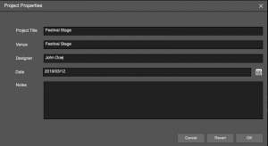
Project Properties
Save
Save the new MAPP 3D Project (.mapp):
- FILE > SAVE PROJECT AS (cmd+shift+S or ctrl+shift+S)
Remember, save early, save often. Creating versioned file names (project v1, project v2, …) serve as intermediate points to go back to during the system design, evaluation, optimization process.
A folder named MAPP Backup will also be created when the project is saved. MAPP 3D auto-saves backups to this folder every ten minutes.
Project Settings
Make project specific and user interface preference selections from the Project Settings window:
- FILE > PROJECT SETTINGS (cmd+shift+P or ctrl+shift+P)
- Units tab – select Distance Units
- Appearance tab – Axis Limits, enter values large enough that all added objects will be within the Axis Limits, maximum 1000m for each axis, can be reduced later
- make other selections as desired
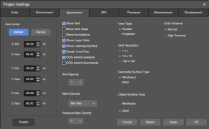
Project Properties
Create Additional Layers
For visibility and lock control, it is helpful to create layers for individual objects or symmetrical pairs of objects to be inserted in the model, following a capitalization scheme reflecting object types (loudspeakers, geometry, microphones), e.g. MAIN L, MAIN R, FRONT FILL, Orchestra 1, Balcony 1, balcony top, balcony bottom.
- TOOLS > LAYER MANAGEMENT
- click ADD LAYER to create several additional layers
- use text capitalization to differentiate layers for different types of objects, e.g., LOUDSPEAKERS/ARRAYS, Geometry, microphones
- layer is selected when objects are added to the model for visibility and lock control
- optional: click color swatches in the color column to edit; color used to represent objects in the model
Objects on locked layers are not selectable or editable in the model or tabs.
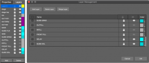
Layer Pane and Layer Management Window
Import Drawings and/or Create Venue Model
Import DXF or SKP files, if available—see Import Drawing link above
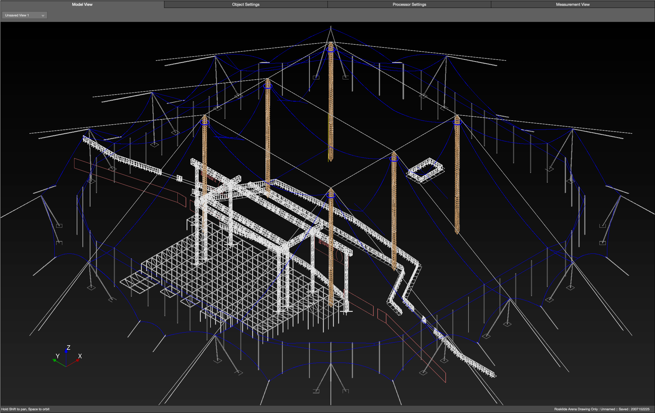
Model Tab – Imported Drawing
Add Primitives / Geometry
Regardless of whether a DXF or SKP is imported, Primitives are added to create geometry, which are selected as prediction planes and are used to display coverage data—see Add Primitives link above.
- add Primitive
- enter name (used for export documentation)
- assign to layer
- edit position and size parameters
- optional: select for prediction
Simpler geometry, for example the listening area of a typical outdoor festival, might best be represented with a rectangle Primitive. More complex geometry, like curved balconies in a theater, might be best represented using the Free Draw tool.
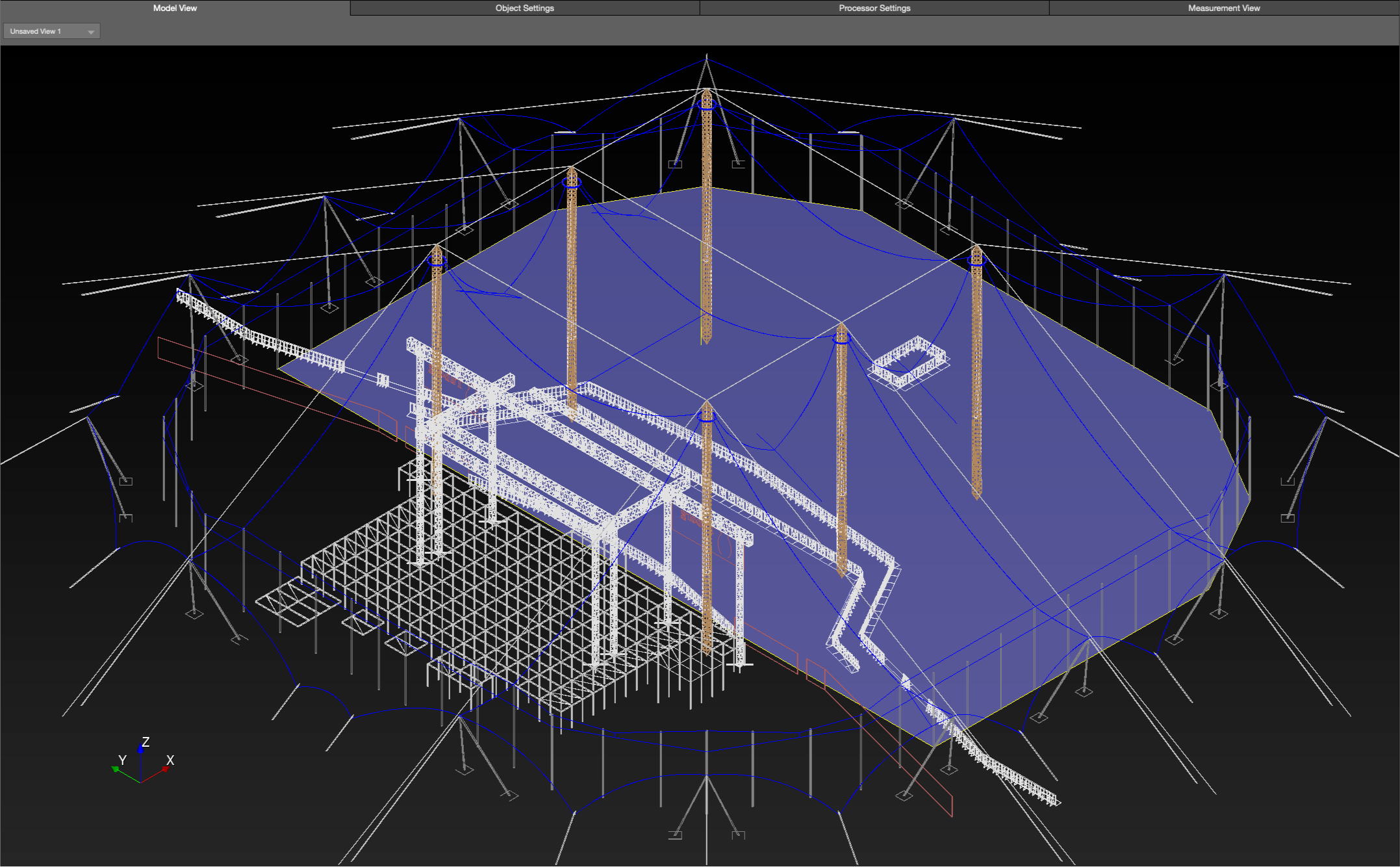
Model Tab – Free Draw Primitive Added as Geometry
If a DXF or SKP is imported, there is a Snapping feature that allows Free Draw vertices to snap to points in the imported file, right-click and choose SELECT SNAPPING TOOL.
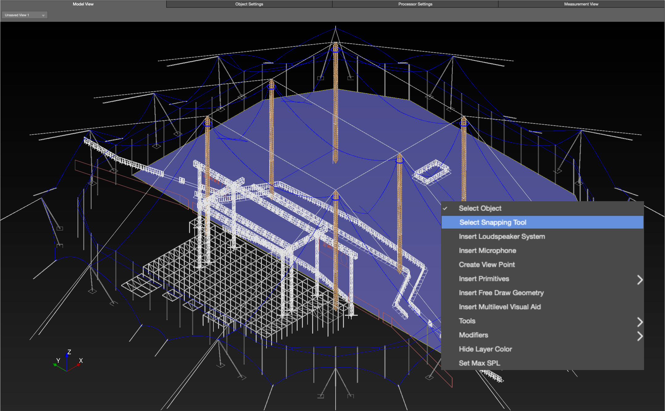
Model Tab – Enable Free Draw Snapping to Imported Drawing Mid- and End-Points
Add Processors
When loudspeakers are added, processor outputs are assigned—see Add Processors link above. Add and label processor outputs before adding loudspeakers.
- INSERT > SIGNAL PROCESSOR
- add desired model(s) of Galileo GALAXY signal processors
- Processor Settings tab
- Select processor from drop-down
- enter name (used for export documentation)
- label the outputs (used for export documentation)
To edit:
- Processor Settings tab, select processor from drop-down
- Express Settings pane, select processor from drop-down
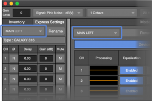
Express Settings Pane – Processor, Processor Settings Tab
Add Loudspeakers
Add loudspeakers or arrays and configure them for best performance—see Add Loudspeakers link above for type details.
INSERT > LOUDSPEAKER SYSTEM or right-click in model, select INSERT LOUDSPEAKER SYSTEM
- select Loudspeaker Type
- enter name (used on export documentation)
- assign to layer
- enter coordinates and rotation
- assign to processor and output channels
- change additional parameters
The optimization process usually involves analysis of the loudspeaker configuration (processing, splay angles, location, etc.) and the resulting response, then modification if needed.
To edit:
- select in Model View tab or Inventory pane
- edit in Object Settings tab or Express Settings pane
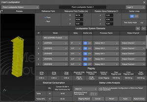
Insert Loudspeaker System – Flown Loudspeaker System
Add Microphones
Microphones provide broadband sample points for analysis in the MEASUREMENT VIEW tab.
INSERT > MICROPHONE or right-click in model, select INSERT MICROPHONE
- insert in logical order, e.g., front to back, left to right, start at the stage or rear of the audience area
- name microphone for recall in Measurement View and exports, e.g., orch rear, orch mid… or balc1, balc2…
- assign to layer
- edit coordinates, usually placed at ear height
Microphones are represented to scale in the model, they are small. It is sometimes helpful to hide geometry layers or select them in the Inventory pane to more easily locate or view.
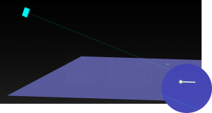
Model View – Inserted Microphone
Optimize System Design Using Model View and Measurement View
The performance and interaction of sound sources can be optimized using MAPP3D’s prediction capabilities. Position, orientation, spacing, and signal processing of various sound sources can be adjusted and the results viewed as pressure plots on prediction planes. Use pressure plots to analyze coverage, up to one-octave wide, in the intended coverage area.
Pressure plots can be displayed as SPL or Attenuation, FILE > PROJECT SETTINGS or right-click in model, select SET MAX SPL.
- SPL values are valid for the range of frequencies predicted, not broadband SPL.
- Attenuation mode plots the loudest point on all of the prediction planes with the 0dB color; lesser levels are plotted using the colors related to attenuation level relative to the loudest point.
- Change Resolution preference to change the number of colors used. 1dB, 3dB, and 6dB options are helpful for visualizing 6dB down points in coverage area.
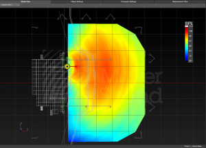
Model View Tab – SPL Pressure Plot on Geometry Selected for Prediction
Measurement View
When microphones are added in strategic locations, the broadband response of the system or sub-system can be analyzed as either a transfer function (Frequency and IFFT Response tab) or as the broadband peak and average response (Headroom tab). Use the Headroom tab to view available headroom and predict maximum output. Adjust the Generator Level and select the test signal type for further analysis.
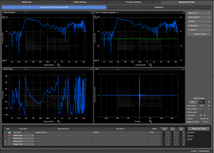
Measurement View Tab – Frequency Response and IFFT Tab
Export Project Information
When the design is finalized, project information can be exported including: a loudspeaker system report, screenshots, microphone data, equipment list, patch list, and a DXF of the loudspeakers and arrays in the model.
Synchronize MAPP 3D and Signal Processor(s)
Galileo GALAXY processors can be connected to the MAPP 3D application for bi-directional control. When connecting, settings can be pushed from MAPP 3D to the processor or pulled from the Galileo GALAXY processor into MAPP 3D to synchronize the processor settings. Once synchronized, the processor controls are bi-directional.
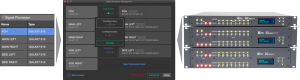
Inventory – Signal Processor Tab, Signal Processor Management Window, Galileo GALAXY Signal Processors
What’s Next?
Please see Import Drawing next. If drawings are not available, please see Navigation next, which covers modification of the model appearance in the Model View tab and how to Select objects.