Page Contents
Application Navigation and Interface
Application Appearance
The main application window has four sections. Double-click the left and right sidebar separators to hide/show these sidebars.
Double-click any tab to un-dock it from the main application window. Double-click the top bar of a window to re-dock it in the main application window.
Keyboard
When editing values, type numbers in the entry field or select the value (double-click), then use the UP/DOWN keys to increase and decrease the value.
To move focus between entries, use the TAB key to advance to the next entry, SHIFT-TAB to move to the previous entry.
Keyboard shortcuts are in More menu above.
Coordinate System
The three dimensional model space of MAPP 3D uses a common universal coordinate system, UCS. Models are usually laid out using:
- X as the up/down stage axis
- Y as the left/right axis
- Z as the vertical axis
Even though other orientations can be used, the object rotations are all relative to the above orientation. Inserting and editing objects will be easier if the above orientation is used.
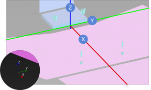
To assist, the UCS reference is always displayed in the lower-left of the Model View and Object Settings tabs.
Toggle the Show Axis preference in FILE > PROJECT SETTINGS > APPEARANCE tab. In the drawing below, Show Axis is on and has been graphically enhanced. The red, green, and blue lines intersect at the zero coordinate of each axis. In this instance, the intersection is at downstage center, where the stage meets the floor.
Coordinate System – Axis Orientation
Select Tool
The Select tool is used to select objects in a model to edit, reposition, delete, or modify. Object(s) need to be on an unlocked layer in order to be selected.
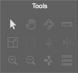
Select Tool
- click the Select Tool
- single object: click on an object in Model View tab
- multiple objects: click-drag a selection box for one or many objects in the Model View tab
NOTE: If multiple target objects are not selectable with a selection box without selecting non-target objects, move the non-target objects to another layer and lock or hide the new layer.
Manual Adjustment of Model View
There are several ways to change the view of the model in the Model View tab.
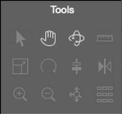
Orbit And Pan Tools
Pan Tool
There are two methods to pan the view in the Model View tab:
- select the Pan tool, using the mouse, click and drag in the model space
- hold down the keyboard SHIFT key, with the mouse, click and drag
Orbit Tool
There are two methods to orbit the view in the Model View tab:
- select the Orbit tool, using the mouse, click and drag in the model space
- hold down the keyboard SPACE BAR, with the mouse, click and drag
Preset Adjustment of View
Camera Selection, Viewport Buttons, Camera Management Window
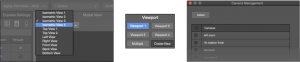
Camera Preset Views
There are presets for common viewing angles.
- change the view from the drop-down in the upper-left of the Model View tab
- select one of the Viewports or Multiple
The Viewport tab has four Viewport preset buttons and the Multiple Viewport button. The view selections are preserved between the four views.
User Defined Camera Presets
The Create New camera view button creates a new camera view in the Camera Management window where Cameras are managed; this window is also accessible via TOOLS > CAMERA MANAGEMENT. Views saved here populate the Camera drop-down in the Model View. Double click names to edit them.
Zoom
The view of the model can be zoomed in and out.
Zoom In/Out Tools
Zoom In, Out, Extents Tools
- click the Zoom In or Zoom Out tool
- click in the model until desired zoom level is achieved
Use the scroll wheel of the mouse to zoom in/out with the cursor hovering on the model.
Zoom to Extents Tool
Click ![]() to zoom out and view all objects of a model.
to zoom out and view all objects of a model.
What’s Next?
Please see Tools / Edit for information about additional tools and items in the Edit menu.