Quickly Draw Venue
In some instances, users need to quickly and accurately build a model in MAPP 3D using measurements taken on site. This page contains information about creating a MAPP 3D model based on site survey distance and angle measurements. Refine and improve these suggestions as needed for specific applications.
Tools Needed
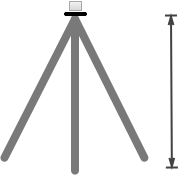
- A laser range-finder and an inclinometer are needed. Several models are available that include both functions. Some models have longer ranges, cameras, and other helpful features, especially for longer distances outdoors in daylight. The accuracy should be less than +/- 0.1 m and +/-0.2 degrees.
- In some cases, a laser-reflective target on a stand is useful, especially when the point of interest is in direct sunlight.
- For many applications, mounting the range-finder/inclinometer on a camera tripod is helpful.
Templates
Create a template to decrease time spent on-site. Include:
- add layers for loudspeakers, geometry, and microphones
- add/label loudspeakers to be used
- add/label processors to be used
- add/label microphones to be used
- adjust Axis Limits to be larger than the venue dimensions (FILE > PROJECT SETTINGS > APPEARANCE tab
Two strategies are used for the seating areas in templates, depending on the seating area elevation:
For seating areas that are on the same horizontal plane (flat floor), adding geometry that is edited while surveying the room is most efficient.
For seating areas that are angled or raked, survey the room and add geometry representing the seating areas as measurements are taken.
Trapezoidal or Rectangular, Non-Inclined Seating
MAPP 3D, Model View – Flat Floor Seating Example
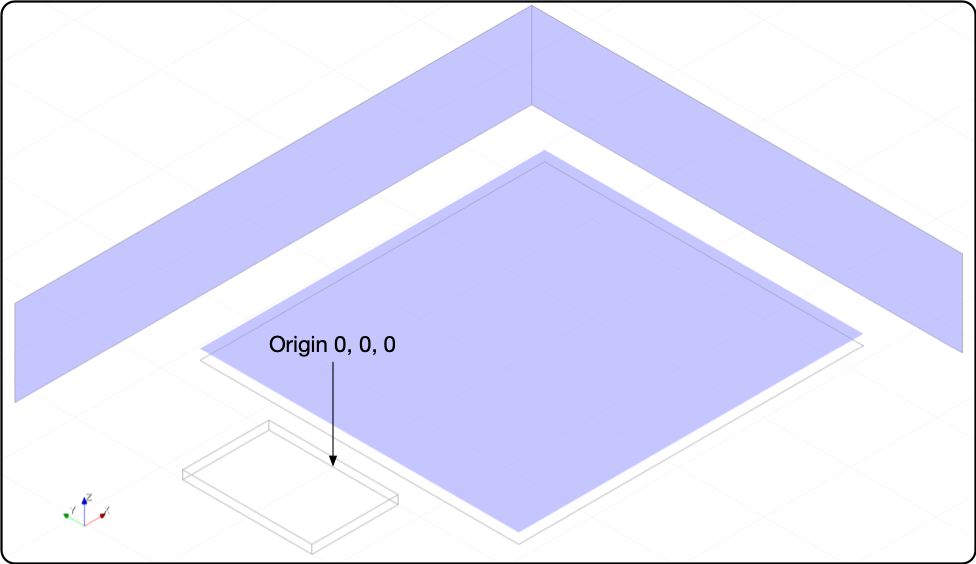
Usually, the origin (X, Y, Z = 0, 0, 0) of a project is downstage center, where the face of the stage meets the floor, on the center line of the room.
Measure the dimensions of the stage, including the height.
MAPP 3D: Add geometry representing the stage using the measurements taken. Move the vertex to the mid-point of the downstage edge. Move the stage so the reference vertex is located at 0, 0, 0.
To modify the reference vertex of geometry: add geometry, right-click on geometry, choose SELECT VERTEX, click on mid-point where the stage meets the floor, right-click and click SELECT OBJECT. Change geometry Position coordinates to 0, 0, 0.
Measure the dimensions of the room, height, length and width.
MAPP 3D: Add geometry for one side wall and the rear wall using the measurements.
Measure the dimensions of the seating area(s).
MAPP 3D: Add geometry of the seating areas(s) with Z-axis values of 0 m. In the Object Settings View, enter an Offset value at the anticipated ear height of listeners. Use 1.2 m (~4 ft.) for seated audience, 1.7 m (~5.6 ft.) for standing audience.
Geometry is inserted with the default reference vertex in the center of the geometry. When locating the geometry in the model, it may be easier to change the reference vertex to the mid-point of an edge.
Usually, the walls and seating areas are selected for Prediction at different points in the design process. In addition to evaluating coverage in the seating area, it is also important to evaluate the amount of sound reaching the architecture of a room and knowing how acoustically reflective the architecture is. This will further inform loudspeaker model selections and aiming choices. To increase intelligibility, minimize sound reaching acoustically reflective surfaces.
Trapezoidal or Rectangular, Inclined Seating
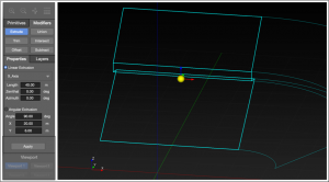
Multi-Level Visual Aids (MLVA) are used to create geometry representing a seating area who’s elevation is not practically measured in the field. A Reference Point is chosen, distance and angle measurements are taken, and entered in a pop-up dialog. MAPP 3D creates a Free Draw object based on those measurements.
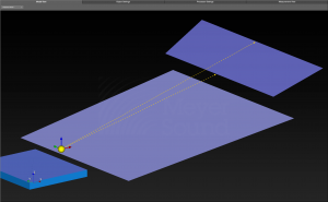
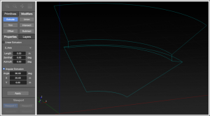
MAPP 3D, Seating Sections Added with Multi-Level Visual Aids
MAPP 3D: As with non-inclined seating, add geometry representing the stage and walls.
Select a location on the center line of the room at or near the downstage lip from which to measure the seating geometry with the laser range-finder/inclinometer, making sure the location is within line-of-sight with the first and last seats of each seating area.
In this example, 0, 0, 2.5 m is downstage center, 1.5 m above the 1.0 m tall stage, to have line-of-sight with the first and last seats of each seating area.
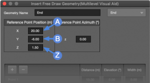
MAPP 3D: Select INSERT > MULTI-LEVEL VISUAL AID and enter the coordinates of the Reference Point Position. Name the geometry and select a Layer.
Measure the width of the seating area at the front and rear of each seating area.
25 m and 28 m for this balcony.
MAPP 3D: Enter the width for each Point.
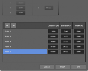
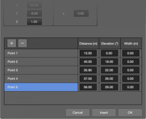
Measure the distance and angle from the Reference Point Position to the top of the backs of chairs in the first and last rows of a seating area.
By default, two Points are added. For contiguous seating areas that have multiple seating angles, add points using the ![]() buttons, take additional measurements, and enter them.
buttons, take additional measurements, and enter them.
The geometry added represents the height of the backs of the chairs. The prediction plane can be offset from the geometry, typically 0.3 m (1 ft) above the seats to represent typical listener ear height.
MAPP 3D: Enter the Distance and Elevation in degrees for each Point.
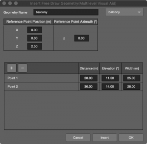
MAPP 3D, Insert Free Draw Geometry (Multilevel Visual Aid) – Balcony Measurements
MAPP 3D, Model View – Multilevel Visual Aid Added as Free Draw Geometry, Point 1 and Point 2
If not taking measurements facing directly downstage on the center line of the room, enter the degrees of rotation in the Reference Point Azimuth field, the Z-axis rotation.
There are several survey techniques to determine this angle, e.g. the Law of Cosines or using a Theodolite.
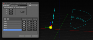
Click INSERT to preview the new geometry. Click OK to convert the Multi-Level Visual Aid to a Free Draw object.
To edit the geometry, select the geometry to change the Reference Point coordinates, Rotation, and the coordinates of each geometry segment in the Properties tab (right pane) or the Object Settings tab.
Curved Seating
There are several instances of seating areas that have curved shapes. To represent a seating area where one side is curved, one method is to add geometry overlapping with the seating area geometry. Then, using the Subtract modifier, the added geometry removes both the added geometry and the area that overlapped with the seating area geometry. This is one version of what is sometimes referred to as the “cookie cutter” method.
The Subtract modifier requires that both geometries are 3D and are on the same Layer. 2D objects, in this case the seating area, can be extruded by a very small distance, 0.05 m for instance. This enables the use of the Subtract modifier.
For a rectangular seating section that has a curved area close to the stage, add geometry to represent the seating area. Then add geometry that overlaps the seating area, in this case an Ellipse. Extrude both to make geometry 3D. Offset the Ellipse in the Z-axis, so the two geometries intersect. Select both the Ellipse and Rectangle. Select Subtract Modifier. Click the Ellipse. Both the Ellipse and the overlap area are removed.
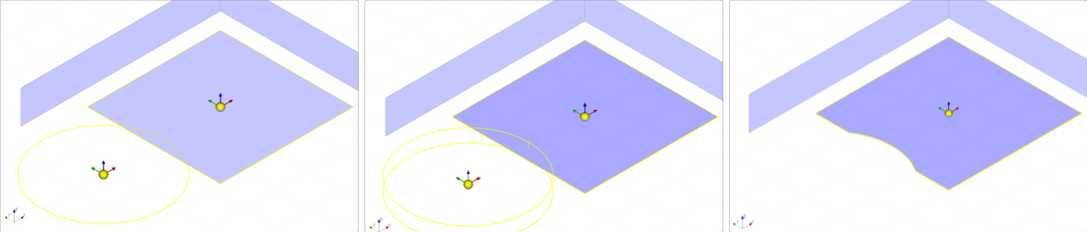
MAPP 3D, Model View – Use 3D Geometry to Modify Another 3D Geometry
There are two ways to determine the size and location of the cutting geometry:
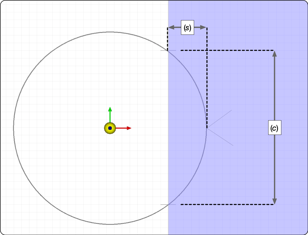
Rough it in: Measure the portion of the seating area to remove: distance across the curve (c) and the depth of the curve (s). Using the Free Draw tool, add lines to the model at these locations. Add an Ellipse to the model and modify it’s properties until it intersects the marked locations. Then use the Subtract Modifier to remove the overlap area. This is approximate and quick.
MAPP 3D, Model View – Add Free Draw Lines as Reference and Modify Ellipse to Meet Reference Lines
Calculate: Measure the “width” and “depth” of the area to be removed (sagitta and cord, below). With these distances, the location and radius of the Ellipse are calculated.
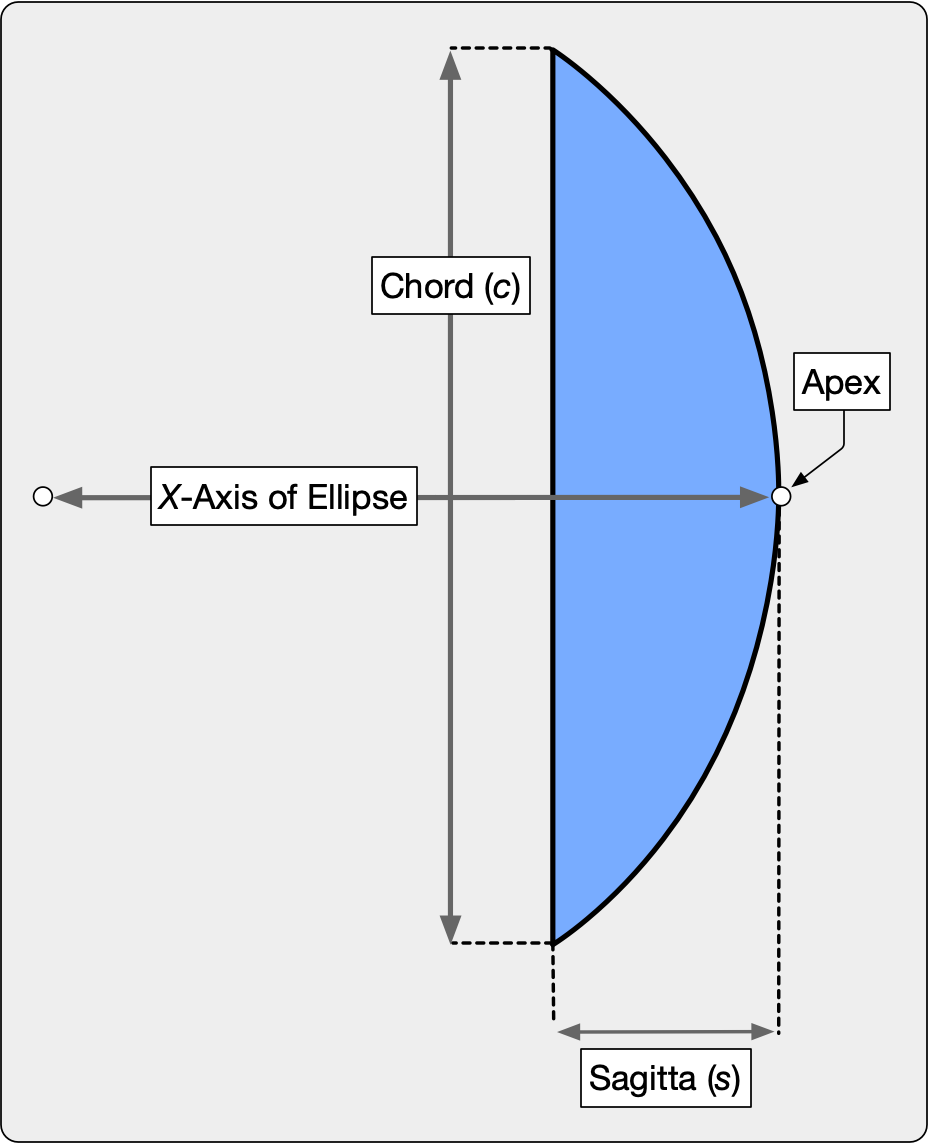
Solve for X-Axis Coordinate of Ellipse
In this example, s = 5 m, c = 20 m, and the X-coordinate of the Apex is 8 m. Using the formulas below, solve for the radius, Ellipse diameter, and the X-coordinate of the Ellipse.
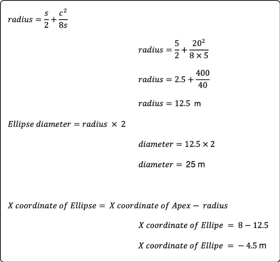
Formulas to Calculate Ellipse Diameter and X-Axis Coordinate of Ellipse
MAPP 3D: Add the Ellipse and enter the Ellipse Diameter in the D1 and D2 fields in the Properties pane. Enter the X coordinate calculated above as the X Position of the Ellipse. Ensure the Y and Z Positions are set to zero. Then, use the Extrude Modifier to make the Ellipse 3D (Linear, Z-axis, 4 m in the example) and modify the Z-axis of the Ellipse/Cylinder so it intersects the seating geometry instead of sitting on top of it (Z-axis, down 2 m, below). Next, select the seating geometry and use the Extrude Modifier to make it 3D (Linear, Z-axis, 0.05 m in this case). Select both the seating geometry and the Ellipse, select Subtract Modifier, then click the Ellipse to remove it and the overlapping area of the seating geometry.
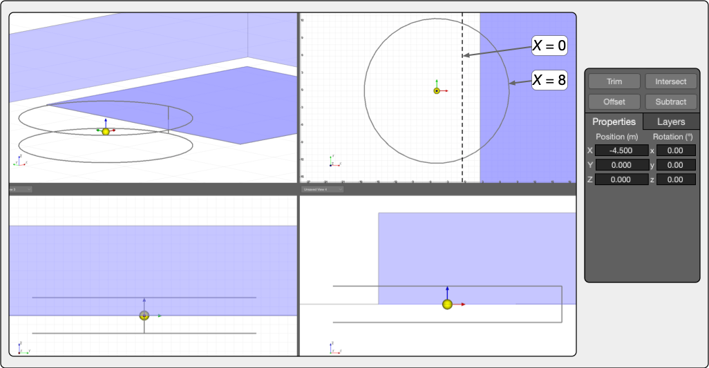
MAPP 3D, Model View – Seating and Ellipse Extruded, Ready to Use Subtract Modifier to Remove Ellipse and Overlap Area from Seating Area
Curved Balcony
Curved balconies can be surveyed and added to a MAPP 3D model. Using the same concepts as above, an Ellipse geometry is added and overlapped with a geometry created using the Multi-Level Visual Aid, then using the Subtract Modifier, the Ellipse and the overlapping area are removed.
Symmetrical Arena
These instructions assume that the Architectural Profile, the shape of the seating area, is symmetrical around the entire arena.
Another way to use Multi-Level Visual Aids (MLVA) is to draw a single Free Draw line representing the section view of a seating area, an Architectural Profile. Extruding the Architectural Profile creates the seating areas and architecture.
It is usually more efficient to measure and record the distances and angels, then use the measurements while building the model in MAPP 3D. Users may find that in some circumstances, the workflow is improved by entering measurements directly in MAPP 3D.
This model can be measured and a MAPP 3D model created in about 10 minutes when the process becomes familiar.
Measure Arena Floor
Measure and the length X and width Y of the arena floor. Where they intersect is coordinate 0, 0, 0 in the MAPP 3D model (O for origin). From the origin, right and up are positive X/Y coordinates, left and down are negative X/Y coordinates.
There may be hockey dashers that define the floor, if not, use the first row of seating for the dimensions of the arena floor.
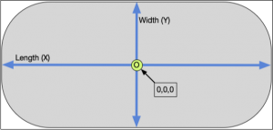
Measure Arena Floor, O = Origin, 0,0,0
Locate Reference Point Position
Move the laser target to the location where the curve of the corner seating becomes straight on both sides of the corner (R for Reference Point).
The Reference Point Position is the location from which the Architectural Profile will be measured.
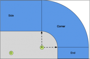
Place Tripod Where Corner Curve Stops on Both Sides of Corner
Measure the distance from x = 0 m to R and record the distance as A.
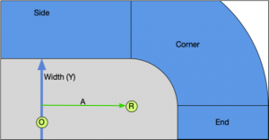
Measure Distance (A)
Measure the distance from y = 0 m to R and record the distance B.
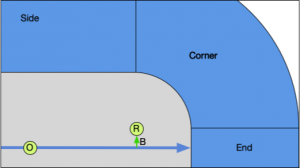
Measure Distance (B)
Measure and record the height of the tripod mount to the floor as distance Z.
Tripod with Target, Measure Height (Z)
Measure Seating and Architecture
Locate the range-finder/inclinometer on a stand at location R.
Measure the beginning and end of each seating section and architectural feature starting at the lowest elevation.
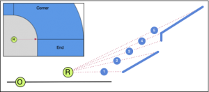
Measure and Record Distance and Angle to Beginning and End Points of Seating and Architecture
Add MLVA for Corner
MAPP 3D: Select INSERT > MULTI-LEVEL VISUAL AID or right-click in the model, select INSERT MULTI-LEVEL VISUAL AID.
Enter Geometry Name and select a Layer from drop-down.
Enter the Reference Point Position coordinates using measurements A, B, and Z.
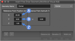
MAPP 3D, Multi-Level Visual Aid – Enter Reference Point Coordinates
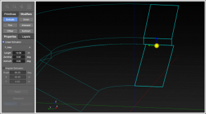
Add points with the ![]() buttons until the number of Points equals the number of Architectural Profile measurements.
buttons until the number of Points equals the number of Architectural Profile measurements.
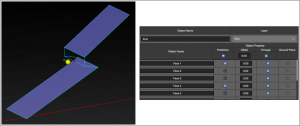
Enter the measured Distances and Elevation angles for each Point. Use the TAB key to move between fields.

MAPP 3D, Multi-Level Visual Aid – Enter Distances and Angles
Click INSERT to preview the Free Draw object in Model View. When OK is clicked, the MLVA is converted to a Free Draw object.
If the values entered do not result in the expected shape, review the measurements taken and values entered in the MLVA dialog. Each coordinate of the Free Draw geometry can be edited as needed in the Properties tab.
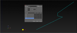
Model View – PREVIEW of Insert Multi-Level Visual Aid
Extrude Corner
Select the Free Draw geometry from the INVENTORY > GEOMETRY list.
Click MODIFIERS > EXTRUDE
Select ANGULAR EXTRUSION
Enter ANGLE = 90 degrees, x = A, y = B, click APPLY
Distances A and B are the x,y coordinates of the Reference Point Position, R.
MAPP 3D, Model View – Modifiers, Extrude, Angular Extrusion and Resulting Object
Add MLVA for Side
For arenas that have a symmetrical Architectural Profile, the side Multi-Level Visual Aid is the same as the corner, except the reference point is moved to allow proper extrusion.
MAPP 3D: Select INSERT > MULTI-LEVEL VISUAL AID or right-click in model space, select INSERT MULTI-LEVEL VISUAL AID.
Enter Reference Point Position coordinates using measurements A, B, and Z.
Change the X value to be negative (later extrusion must be positive).
Enter 90 degrees for the Reference Point Azimuth.
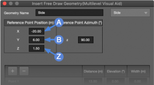
Multi-Level Visual Aid – Enter Reference Point Coordinates, Make X Negative, Azimuth = 90
Enter the Distance and Elevation measurements for each Point.
MAPP 3D, Multi-Level Visual Aid – Enter Distances and Angles
Click INSERT to preview the Free Draw object in Model View.
When OK is clicked, the MLVA is converted to a Free Draw object.
MAPP 3D, Model View – PREVIEW of Insert Multi-Level Visual Aid
Extrude Side
Select the Side Free Draw geometry from INVENTORY > GEOMETRY.
Click MODIFIERS > EXTRUDE.
Select LINEAR EXTRUSION.
Select X-Axis from the drop-down menu.
Enter LENGTH distance, 2 x distance A, click APPLY.
Distance A = X coordinate of the Reference Point Position.
Model View – Modifiers, Extrude, Linear Extrusion and Resulting Object
Add MLVA for End
Select INSERT > MULTI-LEVEL VISUAL AID or right-click in model space, select INSERT MULTI-LEVEL VISUAL AID.
Enter Reference Point Position coordinates using measurements A, B, and Z.
Change the Y value to be negative (later extrusion must be positive).
Multi-Level Visual Aid – Enter Reference Point Coordinates, Make Y Negative
For each Point, enter the Distances and Elevation angles for each Point.
MAPP 3D, Multi-Level Visual Aid – Enter Distances and Angles
MAPP 3D, Model View – PREVIEW of Insert Multi-Level Visual Aid
Extrusion End
Select the Free Draw object from the INVENTORY > GEOMETRY list.
Click MODIFIERS > EXTRUDE.
Select LINEAR EXTRUSION.
Select y Axis from the drop-down menu.
Enter LENGTH distance, distance 2 x B, click APPLY.
B is the Y coordinate of the Reference Point.
Model View – Modifiers, Extrude, Linear Extrusion and Resulting Object
Select Geometry Faces for Prediction
Select the End geometry.
Select Object Settings.
Select Faces for Prediction.
Repeat prediction selection for faces of Side and Corner geometry.
Object Settings – Select Faces for Prediction
Mirror Geometry
Use the Mirror tool to make symmetrical copies of these objects to complete the arena model.
Select the Corner geometry.
Select the Mirror Tool. From the pop-up menu, select MIRROR ALONG Y AXIS and FLIP OBJECT.
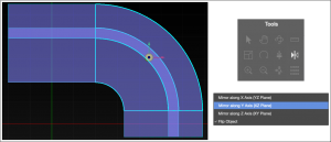
Select Corner, Mirror Tool, Mirror Along Y Axis, Flip Object
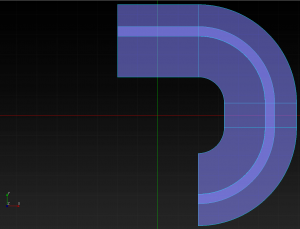
Corner Mirrored Along Y-Axis
Rename mirrored Corner geometry, double-click the name in INVENTORY > GEOMETRY, change the name to Corner 2.
Select the Corner 2 object and Mirror along the x-Axis, rename new object Corner 3.
Select the Corner 3 object and Mirror along the y-Axis, rename new object Corner 4.
Corners 3 and 4 Mirrored
Select the Side object and Mirror along the y-Axis, rename new object Side 2.
Select the End object and Mirror along the x-Axis, rename new object End 2.
Mirror Side and End Objects
Add geometry to represent the floor seating and stage
MAPP 3D, Completed Model with Added Floor Seating and Stage
What’s Next?
Please see Add Processors next.