Page Contents
Add Primitives
Primitives are pre-built blocks used to represent the architecture of a venue. Once in the model view, Primitives are referred to as Geometries. Geometries can be simple Primitives or modified Primitives. Add Primitives to the model to represent a stage, seating areas, and structures of acoustic significance (rear wall, catwalks) or rigging height limitations. Name them, and assign them to layers. Typically, the 0, 0, 0 coordinate is the intersection of the face of the stage and the floor, on the center line of the room.
When a DXF or SKP drawing file is imported, geometry is added and selected for prediction. MAPP 3D renders pressure plots on geometry that is selected for prediction.
Model View – Imported Drawing, Geometry Added
Primitive Types
Four 3D Primitives are available:
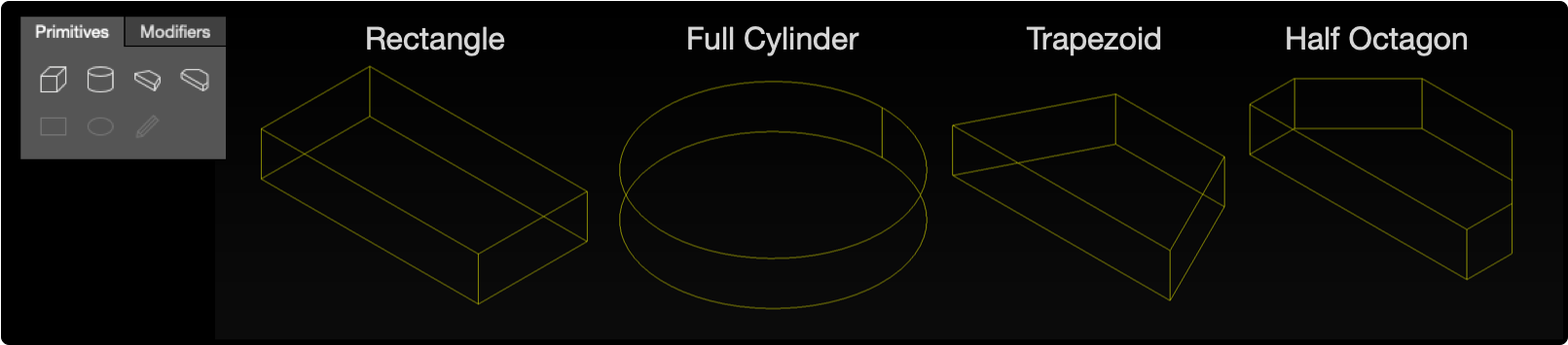
Available 3D Primitives
Three 2D Primitives are available:
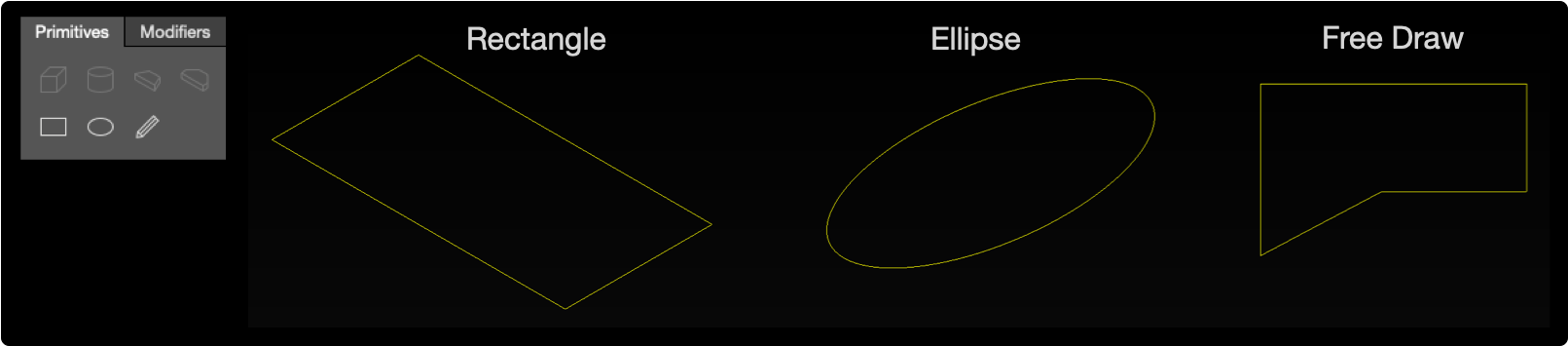
Available 2D Primitives
Free Draw Primitive
The Free Draw Primitive is used to create polylines and asymmetrical shapes in the model.
Insert – Method One
- select the Free Draw tool
- click in the model to create the first vertex
- move to the next vertex location
- repeat to add vertexes
- press “enter” to stop adding vertexes
- press “c” to close the the shape
Free Draw, Add Vertexes – End, Close
Insert – Method Two
- right-click in the model
- select Insert Free Draw Geometry, opens window
- enter coordinates for each vertex (point)
- optional – select a vertex, click
 buttons to add another Point below or remove selected point
 - optional – select Close Geometry to join the last vertex to the first vertex
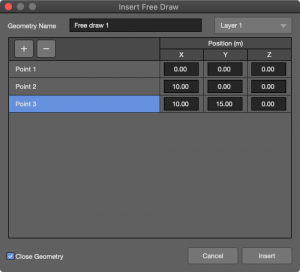
Insert Free Draw Window
Edit Vertexes
In the Properties tab, vertexes of a Free Draw primitive can be edited manually, added, and deleted. Click APPLY to accept changes.
Edit Vertices, Click APPLY
Snapping to Imported DXF or SKP
Free Draw vertexes can be snapped to points of an imported DXF or SKP file.
- right-click and choose SELECT SNAPPING TOOL from the pop-up in model
- hover the mouse near the mid-point or end-point of an imported entity
- click to use create a Free Draw vertex
Repeat to add additional vertexes. If this geometry is extruded 180 degrees, it would represent the seating area. See below, Extrude.
Free Draw – Snapping To Imported Geometry
When adding Primitives, select a non-isometric or “flat” view (Top, Left, Right, Front, or Rear) to add geometry on an axis with a zero value. This is illustrated below:
To Add Primitive Flat on an Axis, Add Primitive in Flat Viewport
Add Other Primitive Types
- select desired Primitive type
- click in the model to add
Add Primitive To Model
Edit Geometry
When a Primitive is added to the model, it is referred to as geometry. All properties of geometry are available in the Object Settings Tab. Also, edit properties in Express Settings and Properties tabs.
- select geometry in model
- click Object Settings tab
NOTE: Zoom, pan, and orbit are available in the preview pane.
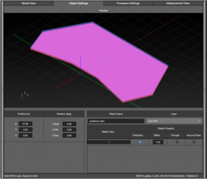
Object Settings Tab, Geometry Selected
- select geometry in model or select from Inventory tab
- use Express Settings pane to change the Prediction and Through preferences
- edit basic properties in the Properties pane
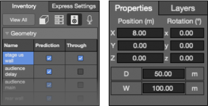
Inventory, Geometry and Properties of Geometry
Change Reference Point of Geometry
The reference point of a Primitive is the center of the Primitive by default. To change the location:
- select geometry
- right-click, choose SELECT VERTEX from the pop-up menu
- click corners, mid-points, incrementally for curves and circles, or the center of the Primitive to select a new reference point
- right-click, choose SELECT OBJECT
- click ENTER
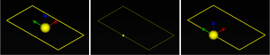
Change Geometry Reference Location
Relocate (Move) Geometry
The location of geometry can be changed in two ways:
Method One
- select geometry
- click-drag the yellow sphere inside the Primitive
- limited by the boundary limits of the model
Move Geometry – Click Object Reference Point and Drag
Method Two
- select the geometry
- edit parameters in Properties Pane or Object Settings Tab
Based on the Primitive type, different properties will be displayed for each type of Primitive. For 3D and 2D shapes, the position coordinates, orientation/rotation around each axis, and dimensions are displayed and can be edited. Position is referenced to the center of the Primitive, unless Select Vertex has been used to choose a different reference point.
Delete Geometry
- select geometry (Primitive)
- press DELETE on the keyboard, also EDIT > DELETE
Other Geometry Properties
Geometry is added to a model with no attributes given to its surface(s). Changes to a Primitive’s surface attributes are made in the Inventory pane or Object Settings tab.
Prediction
Select the Prediction option for a surface—enables pressure plots to be displayed on that surface.
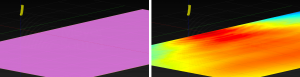
Model View – Geometry Selected for Prediction, Geometry with Prediction
Through
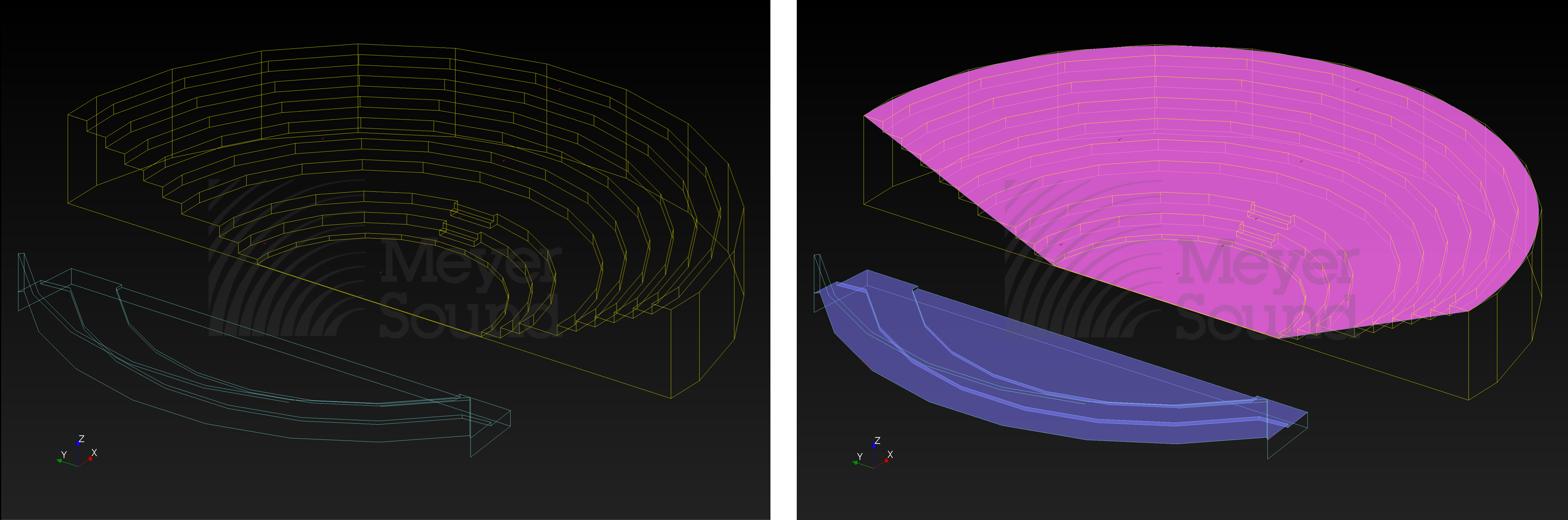
Center lines of loudspeakers will pass through Primitives when they are set to Through (default). When not selected as Through, the Primitive will be pink (or purple if the surface is also selected as Prediction) and the loudspeaker center lines will not go through the Primitive.
This allows designers to determine if the center line of a speaker has line of sight to certain areas (e.g., under balconies).
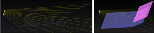
Through Example – Orchestra Through, Balcony Not Selected as Through
Offset
Any Primitive that is selected as Predictive includes the Offset option. The prediction plane will be offset from the geometry by the value entered. This is generally used to approximate actual listening height. The offset value can be adjusted to accommodate seating or standing heights.
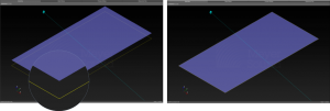
Geometry Offset for Prediction – Offset 1.5m, No Offset
Ground Plane
MAPP3D acoustic data is based on precise measurements of Meyer Sound products. One of the benefits of this precision is that users can replicate and confirm the predictions made in MAPP 3D in the real-world. Because ground plane measurements are often used to capture loudspeaker data, MAPP3D includes a tool to replicate this method for predictions.
When geometry is selected as Ground Plane, a first order acoustic reflection from the geometry is modeled. One geometry in a project can be selected as Ground Plane. This is a perfect first-order acoustic reflection, without acoustic coefficients, no absorption or transmission properties. The intended use is to predict measurements with a microphone on the geometry, replicating a ground plane measurement in an open space, where a loudspeaker is measured with the microphone on the floor or ground. Selecting geometry as Ground Plane does not affect its appearance.
- select geometry in Model View tab
- Object Settings tab
- select PREDICT and GROUND PLANE
- enable ground plane prediction, make selection in EDIT menu, select GROUND PLANE PREDICTION
- select bandwidth and frequency for prediction
- Click PREDICT (cmd-R)
Ground Plane Prediction – Horizontal Geometry Selected as Ground Plan, Vertical Geometry Added for Visualization
Geometry Modifiers
Modifiers can be used to edit single or multiple Primitives to create unique geometry.
Extrude Modifier
Extrudes single 2D geometry to be 3D geometry.
- select 2D geometry
- select MODIFIER tab, click EXTRUDE
- select Linear or Angular Extrusion radio button
- enter desired parameter value(s) or select value and use up/down arrow keys to increase/decrease value – see below examples
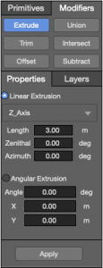
Properties Pane – Extrude Parameters
Linear Extrusion
When Linear Extrusion is selected, choose the axis to extrude the shape along from the drop-down menu. Enter a Length and optionally, a Zenithal and/or Azimuth angle, examples below. Click the APPLY button at the bottom of the tab to extrude the geometry.
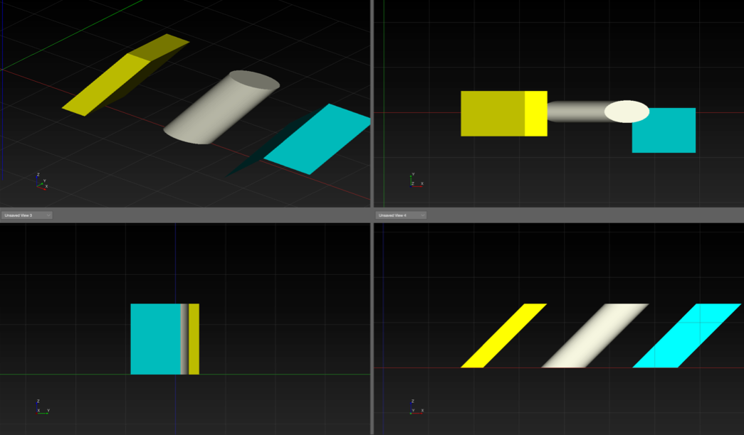
The below examples begin with these three geometries lined up on the positive X-axis.
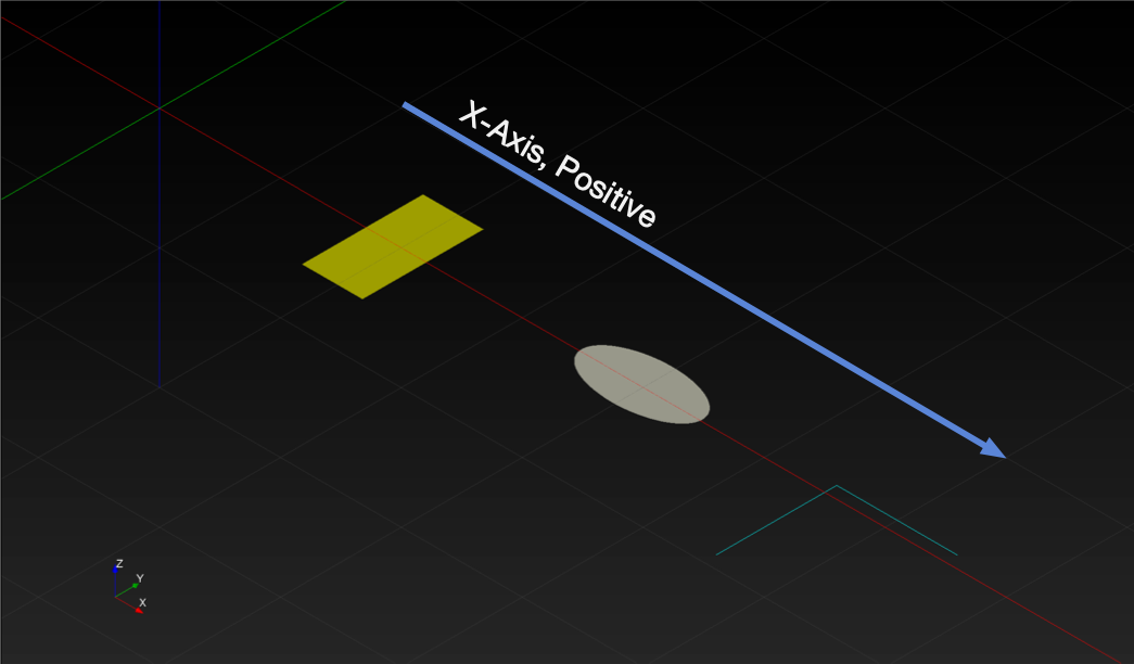
Model View, Linear Extrusion Example – Original Geometry: Rectangle, Ellipse, Free Draw
Linear Extrusion Along Axis Example: Select an axis to extrude along from the drop-down menu. Enter a Length, which is always positive. Click the APPLY button at the bottom of the tab. When these Geometries (below) are extruded along the Z-Axis, the shapes are extruded along the Z-Axis, resulting in 3D geometry.
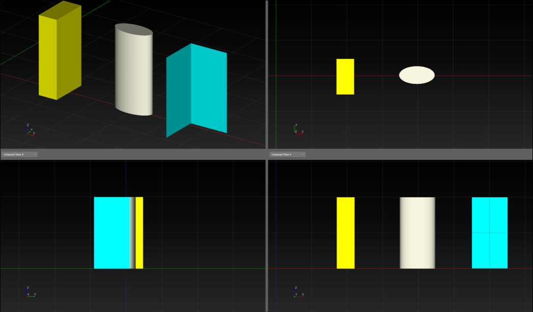
Model View, Linear Extrusion Example, Three, 2D Shapes Extruded Along Z-Axis
Linear Extrusion Along Axis with Zenithal Angle Example: Zenithal angle is constrained between 0-180 degrees. Below are the results when the 2D geometries are extruded with the Zenithal Angle set to 45 degrees.
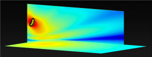
Model View, Linear Extrusion Example, Three, 2D Shapes Extruded Along Z-Axis With Zenithal Angle Set To 45 Degrees
coming soon… Linear Extrusion Along Axis with Azimuth Angle Example: Azimuth angle is constrained between -180 to 180 degrees. Below are the results when these 2D geometries are extruded with the Azimuth Angle set to 45 degrees.
Angular Extrusion
When Angular Extrusion is selected, choose the angle for the geometry to follow while extruded and enter the X and Y coordinates of the center of rotation, examples below. Click the APPLY button at the bottom of the tab to extrude the geometry.
The below examples begin with a Free Draw line with two segments.
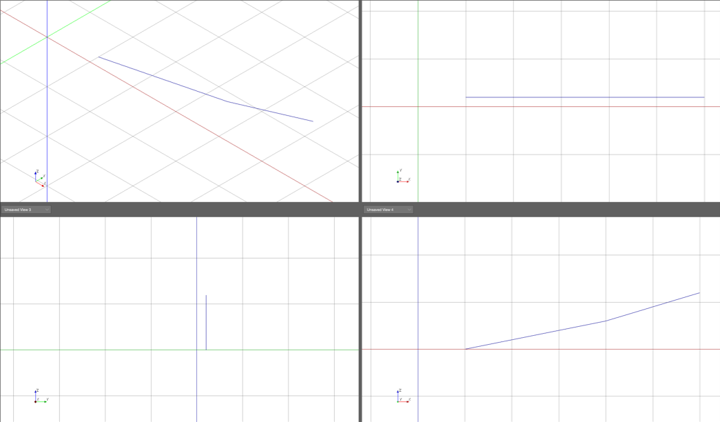
Model View, Angular Extrusion Example – Original Geometry
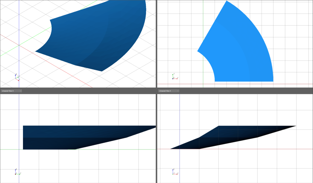
When the Free Draw is extruded 45 degrees centered at 0,0 the shape below is the result.
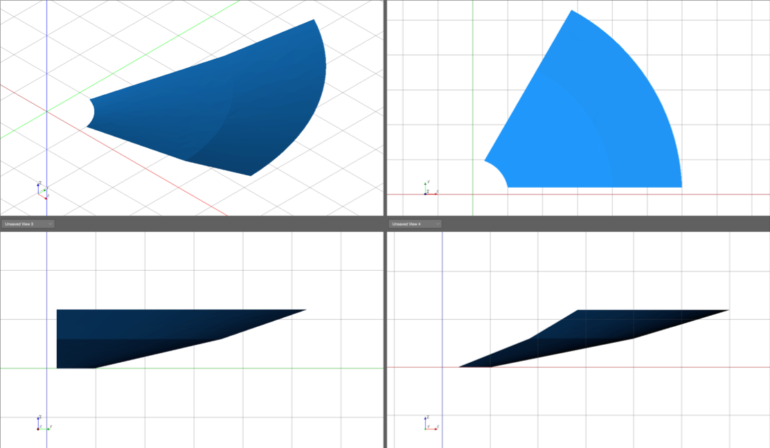
Model View, Angular Extrusion Example – 45 Degree Extrusion, Centered at 0,0
When the coordinates are changed, different shapes are created. This example uses the beginning of the Free Draw as coordinates.
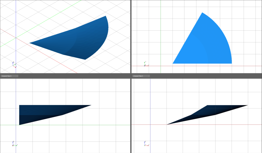
Model View, Angular Extrusion Example, Free Draw Extruded 45 Degrees, Centered at Beginning of Free Draw
Changing the coordinates to be further away on the X-Axis, results in the shape below.
Model View, Angular Extrusion Example, Free Draw Extruded 45 Degrees, Centered Further Away
Trim Modifier
Applies to 2D geometry.
- select two intersecting geometries
- click TRIM
- click geometry to trim
- press ENTER to end trim selection
NOTE: Press ESCAPE to abort.
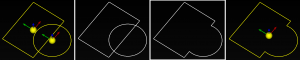
Trim Modifier – Select, TRIM, Click to Remove, ENTER
Offset Modifier
Applies to geometry. Duplicates and offsets the selected geometry at the distance and axis entered.
- select geometry
- click OFFSET
- choose Model View UCS or Object UCS
- enter offset distance for each axis
- click APPLY
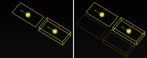
Offset Modifier – Two Examples, 2D and 3D. Original Objects, Original Objects with Offset Objects
Union Modifier
Used to create one 3D geometry from two intersecting 3D geometries.
- select two overlapping 3D geometries
- click UNION
Union Modifier – Two 3D Geometries, Before and After Union
Intersect Modifier
Can only be performed on two 3D Primitives that intersect. This Modifier result is the intersecting volume of 3D Primitives.
- select objects
- click Intersect modifier
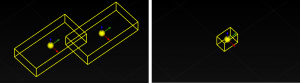
Intersect Modifier – Two 3D Objects Selected, Resulting Geometry
Subtract Modifier
Applies to two intersecting 3D geometries. This Modifier removes the intersecting volume of one of the 3D geometries.
- select both geometries
- click SUBTRACT modifier
- click the geometry being subtracted
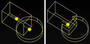
In the below example, the cuboid is clicked to remove its volume from the cylinder.
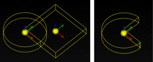
Subtract Modifier – Two Geometries Selected, After Modification
What’s Next?
Please see Add Processors for information about adding processors to the model.