Page Contents
All Settings and Preferences
This section provides the complete list of settings and preferences available in the MAPP 3D application.
Project Settings
FILE > PROJECT SETTINGS Parameters in this window define the workspace and how the application presents data.
Units
Select the preferred unit of measure for each of the listed parameters.
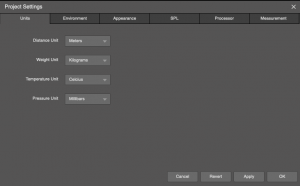
Project Settings – Units
Environment
Temperature, humidity, and altitude settings are used to model high-frequency loss due to air absorption. Select USE AIR ATTENUATION (on by default) to include this feature when predicting.
The source voltage, which affects the current draw estimates, is selected here. Voltage selection can also be changed using the drop-down in the main application window.
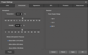
Project Settings – Environment
Appearance
Set Axis Limits boundary limits (size) of the workspace in Model View. These settings control the maximum/minimum XYZ coordinates of the Model. Objects cannot be placed outside of the defined space.
Mesh Density determines the resolution of the SPL map and affects both calculation time and how detailed the map will be. A higher density will ‘sample’ more points on the listening planes, which takes longer and creates a highly detailed pressure plot.
Select Color Scheme as White for better viewing outdoors.
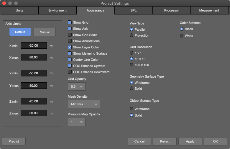
Project Settings – Appearance
SPL
When SPL units are selected, absolute SPL values within the selected range (e.g., for one octave, centered at 4 kHz) will be plotted on the listening planes. When Attenuation is selected, levels will be displayed as relative attenuation from the loudest sound source (similar to MAPP XT). Resolution determines how SPL maps are displayed—full resolution, or various increments in level with each color change.
This tab can also be accessed directly by right-clicking in Model View and selecting Set Max SPL.
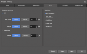
Project Settings – SPL
Processor
When selected, Atmos. Corr. Response enables the display of the compensation filters in the Processor Settings tab used to correct for high frequency air absorption.
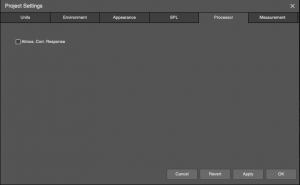
Project Settings – Processor
Measurement
These preferences change the plotting scales in the Measurement View tab. These parameters can also be changed in the Measurement View tab by clicking icons next to the plotters.
Select ENABLE WINDOW CENTERING to vertically center amplitude plots.
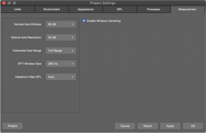
Project Settings – Measurement
View Menu
Use the View menu to choose optional items shown in the Model View tab. Click on an item to toggle on/off.
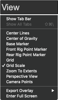
View Menu
Center Lines
Center Lines indicate the direction a loudspeaker is pointing. This is the global control. Each loudspeaker or loudspeaker array also has a center line preference, changed either in the Express Settings tab or Object Settings tab.
Geometry has a preference for Through. When selected, the center lines will go through the geometry. If not selected, the center line will terminate at the geometry. This is useful to determine if there is line of site between a loudspeaker and a seating area (for example, under-balcony seating).
Center Lines Selected, Balcony Not Selected Through, Orchestra Selected Through
Center of Gravity (COG)
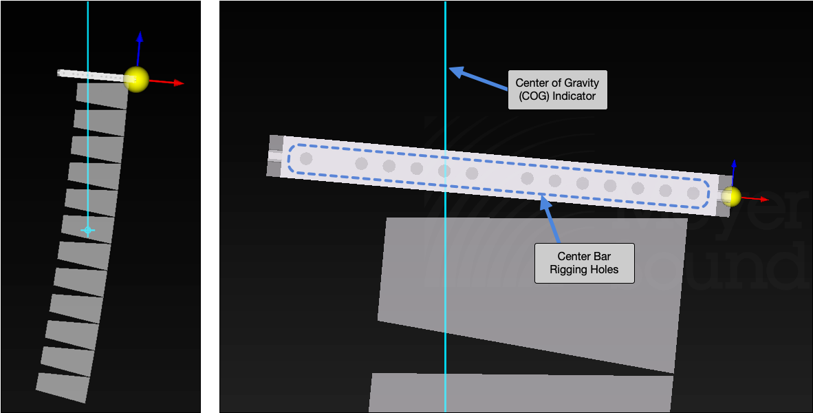
Center of Gravity Indicator
When selected, Center of Gravity (COG) turns on the indicator in Model View. Used to determine minimum/maximum uptilt or downtilt of array grids. Used to determine which center pick-up point to use to achieve a specific up/downtilt of grids with center pick-up bars. Select array to view intersection of COG marker and rigging holes of center bar.
Base Marker
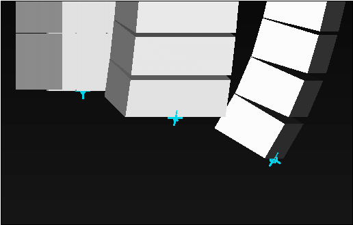
Base Marker Indicator
For loudspeaker arrays in Model View, the Base Marker indicates the point on the vertical axis (Z) of an array closest to the Z plane (usually the floor or ground).
Front/Rear Rig Point Marker
When selected, indicates the front and/or rear rigging point of a grid used to suspend a flown loudspeaker array.
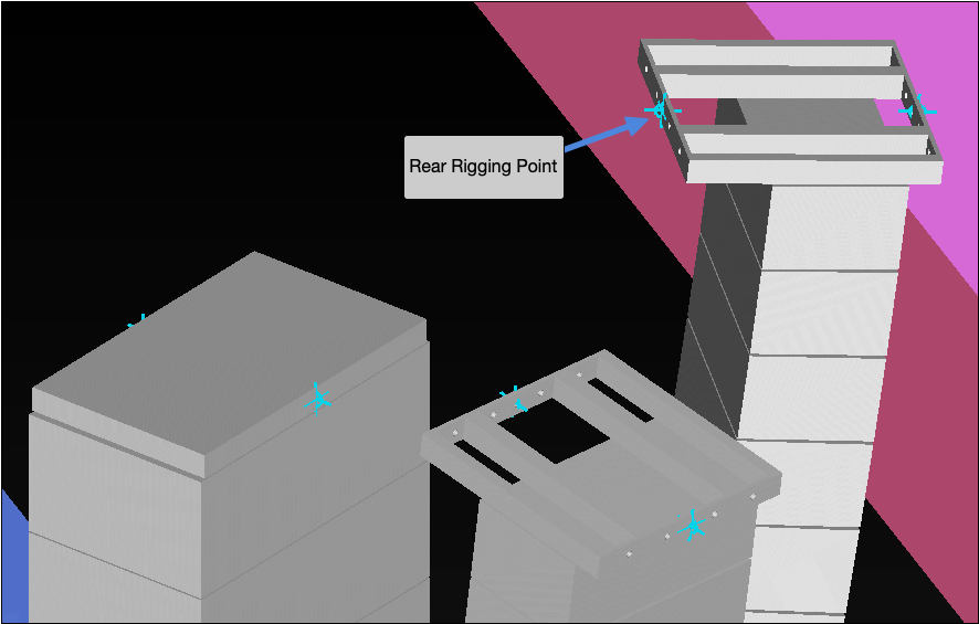
Front and Rear Rigging Point Indicators
Grid
In Model View, toggles reference grid on/off. Also found in FILE > PROJECT SETTINGS, Appearance tab: with Resolution, Scale, and Opacity preferences
Grid Scale
In Model View, toggles numeric labeling of grid lines at boundary of pane. Also found in FILE > PROJECT SETTINGS, Appearance tab
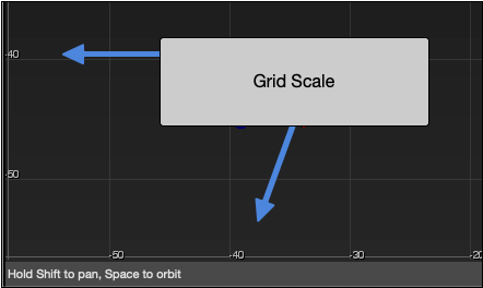
Grid Scale
Zoom to Extents
In Model View, zooms to include all objects in the model.
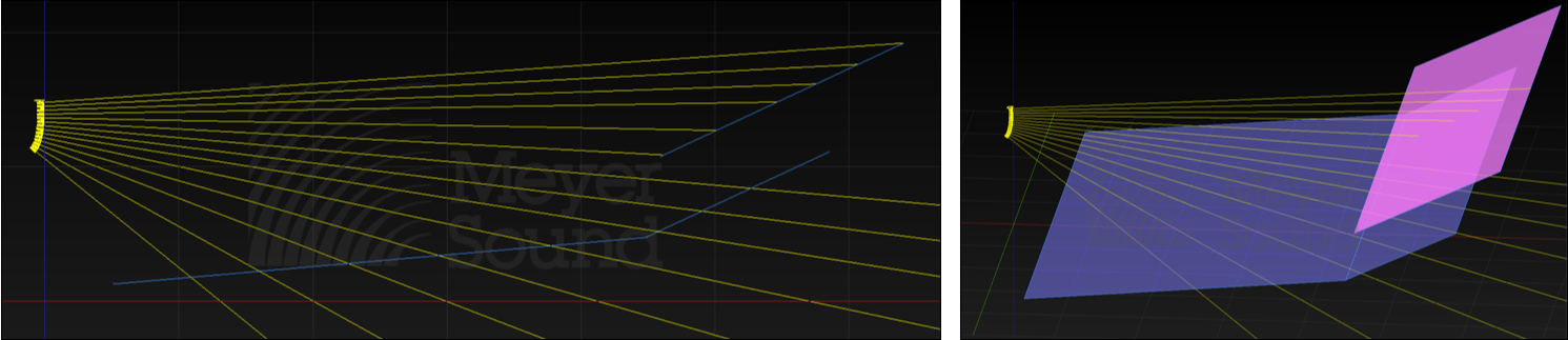
Perspective View
By default, Model View displays a parallel view. Zoom in/out when in top, bottom, left or right views does not change the appearance. For a more 3D view, select Perspective. When zoomed in/out, the appearance is similar to that of reality.
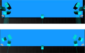
Model View – Perspective View (top), default Parallel View (bottom)
Camera Points
Displays the camera locations for cameras that have viewpoints within the axis limits, shown as grey pyramids. The default camera views are not displayed. User created cameras are displayed.
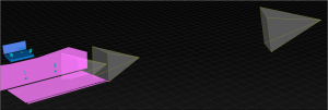
Model View – Three Camera Points
Export Overlay
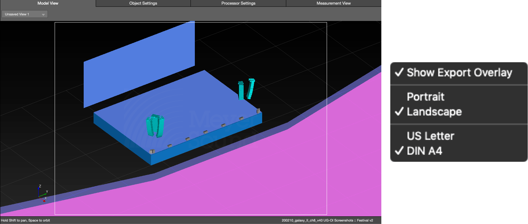
Model View – Export Overlay Selected
Adds a highlight box to the Model View tab to indicate the area of the window that will be exported. Select orientation and size from the sub-menu.