System Design and Prediction Tool
Welcome to Meyer Sound Labs MAPP 3D Help and Instruction pages! The drop-down menus above are structured from left to right to present instructions in a logical, progressive order.
For those users familiar with MAPP XT, MAPP 3D offers significant improvements:
- 3D model building
- no Internet connection required for prediction
- bi-directional control of Galileo GALAXY signal processors
- simultaneous import of both DXF and SKP drawings
- high-resolution, 3D loudspeaker data sets from our anechoic chamber
- multi-level auto-splay for flown loudspeaker systems
- maximum electrical consumption calculation
- adjustable generator gain and signal type
- improved editing speed of loudspeakers, processors, and geometry
Contact
We appreciate hearing from our customers! If you have suggestions on improvements to MAPP 3D, or other software products, please share them with us. While we can’t respond to every suggestion, we will evaluate each one for implementation. When submitting feature requests and bug reports, please visit meyersound.com/contact, select Technical Support, and use the form to submit feedback.
For personal assistance, please visit meyersound.com/contact, select Technical Support, and use the form to create a support case.
Videos
These webinar videos describe the basic functions and operation of MAPP 3D using a simple venue example.
User Interface Overview
Add Primitive/Geometry, 3D Example
Import Drawing
Insert Loudspeaker System
2D Prediction in 3D Space
Add Geometry and Extrude
Auto-Splay
Predict Results in Model View
Predict Results in Measurement View
Processors and Sync with Compass Software
Add Fill Loudspeakers
These are the roundtable discussions, presentation followed by questions/answers.
Roundtable #1 Help, Feature Requests / Bug Reports, Main User Interface, Viewports, and Importing Drawings
Roundtable #2 Insert Objects & Geometry, Change Geometry Reference Point, Modifiers, SPL vs. Attenuation in Model View, and Optimization Strategies for Faster Predictions
Roundtable #3 Headroom (Delta dB) and Processor Linking
Roundtable #4 Design Methodologies and Reviews
Overview
MAPP 3D presents users with an intuitive interface to create 3D models of venues, add loudspeakers and microphones, and optimize a system design using Meyer Sound Labs products. This page provides detailed information about the MAPP 3D interface and functions.
Operating Systems
MAPP 3D runs on the current versions of MacOS and Windows operating systems. Though it may operate on earlier operating system versions, proper operation has not been tested.
Video Monitor Display
MAPP 3D supports 1280×768 up to HD and Retina resolution displays. Higher resolutions may scale incorrectly or cause application instability. Please update graphics drivers to the latest version, which may enable 4k resolution.
Welcome Window
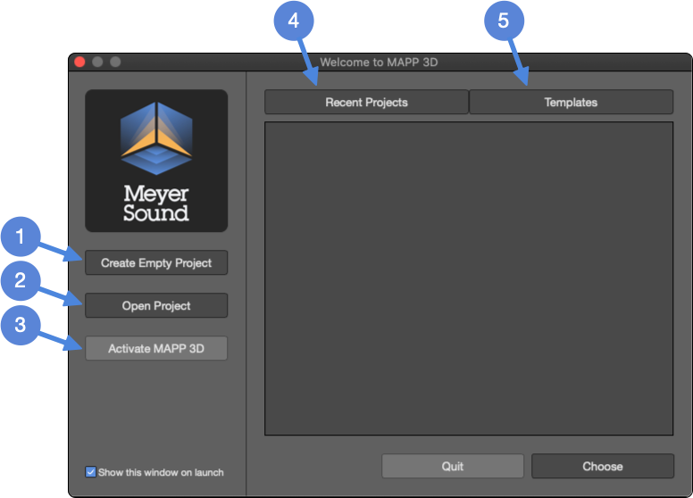
Welcome Window – Opens On Application Launch
The Welcome Window offers several options:
Click CHOOSE after selecting a recent Project or Template. Click CANCEL to close the application.
Project Properties
When a new project is created, the Project Properties window is displayed. Basic information about the project and venue can be recorded here. This information is saved as part of the project file (.mapp).

Project Properties
Main Application Window
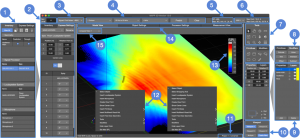
Main Application Window
Inventory/Express Settings Tabs
Inventory: View All selected; click icons ![]() to display only Geometry, Signal Processors, Loudspeaker Systems, or Microphones.
to display only Geometry, Signal Processors, Loudspeaker Systems, or Microphones.
Express Settings: Use the drop-down at the top of the tab to select an object; displays the common properties for editing. For all object properties, use the Object Settings tab.
Generator Gain Level
Adjustment of signal level for all loudspeakers in model; affects SPL values.
Generator Signal Type
Pink Noise, B-Noise, or M-Noise; see definitions.
Pressure Map Settings
Select bandwidth, frequency range, and center frequency of prediction (SPL values valid only for bandwidth and frequency selected—use Headroom Tab for broadband SPL).
Click PREDICT to generate an SPL/Attenuation map for any geometry that has been selected for prediction in the geometry’s Object Settings. Click CLEAR to remove all of the prediction data.
SPL Data
Displays Maximum and Minimum dBSPL(z-unweighted) and the SPL difference across selected prediction planes.
Power Calculation
Select to open the Amperage and BTU calculator at meyersound.com to calculate system current requirements and thermal dissipation.
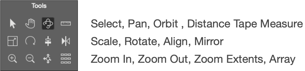
Tools
Select, Pan, Orbit, Distance Tape Measure, Scale, Rotate, Align, Mirror, Zoom In, Zoom Out, Zoom to Extents, and Array.
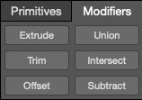
Primitives/Modifiers Tabs
Primitives: select 2D/3D Primitive presets or Free Draw to add to model.
Modifiers: provides tools to modify 2D/3D Primitives.
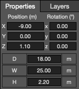
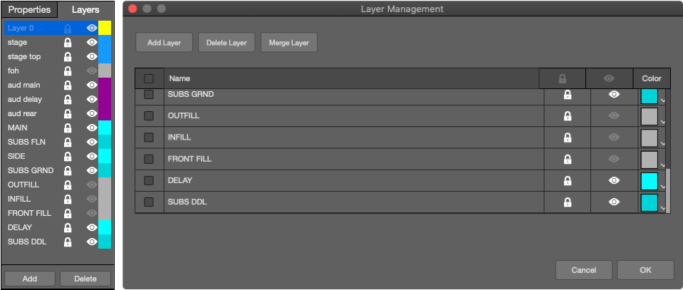
Properties/Layers Tabs
Properties: select Geometry in Model tab; displays basic settings of selected Geometry; can edit.
Layers: click name once to select as current; can rename; provides lock/unlock, show/hide, ADD and DELETE buttons.
Viewport
Select view displayed in Model tab; click CREATE NEW to open Camera (View Point) Management window.
Project File Name
Displays current Project file name.
Contextual Pop-Up Menu
Right click in Model to open. Left, standard menu. Right, with imported drawing, includes Select Snapping Tool.
SPL/ATT Scale
Sound Pressure Level or Attenuation Scale: selected via FILE>PROJECT SETTINGS, SPL Tab. SPL plot values are only for the selected bandwidth, up to one octave wide.
Main Tabs
Select Model View, Object Settings, Processor Settings, or Measurement View.
View Preset Drop-Down
Select view (camera) position from the default or custom views (created by clicking CREATE NEW in Viewport tab).
Main Window Tabs
At the top of the Main Window, there is a row of tabs used to switch between Model View, Object Settings, Processor Settings, and Measurement View ![]() .
.
NOTE: Tabs can be un-docked from the application window by double-clicking the tab. To re-dock the tab, double-click the top bar of the un-docked tab.
Model View
Displays the Model Space, including any geometry, loudspeakers, microphones, and imported graphics. Change the view using the drop-down in the upper left ![]() or the Viewport controls
or the Viewport controls ![]() .
.
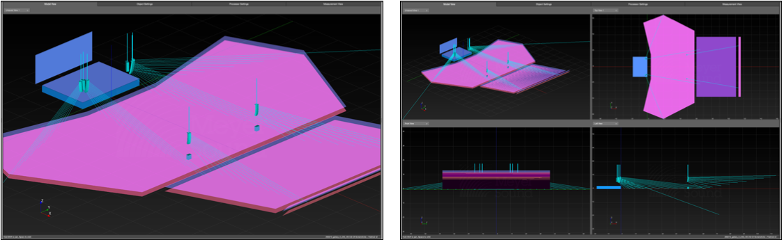
Model Tab – Single Viewport, Multiple Viewport
Object Settings
Displays editable properties of geometry, loudspeakers, and microphones. Select one object in the Model tab, switch to Object Settings tab. Objects on locked layers are not editable.
Object Settings Tab – Select One Object In Model Tab, Switch to Object Settings Tab
Processor Settings
Displays control points for signal processor parameters. These controls can be bi-directional with Compass to control the settings of a Galileo GALAXY processor. Use TOOLS > SIGNAL PROCESSING MANAGEMENT to link.
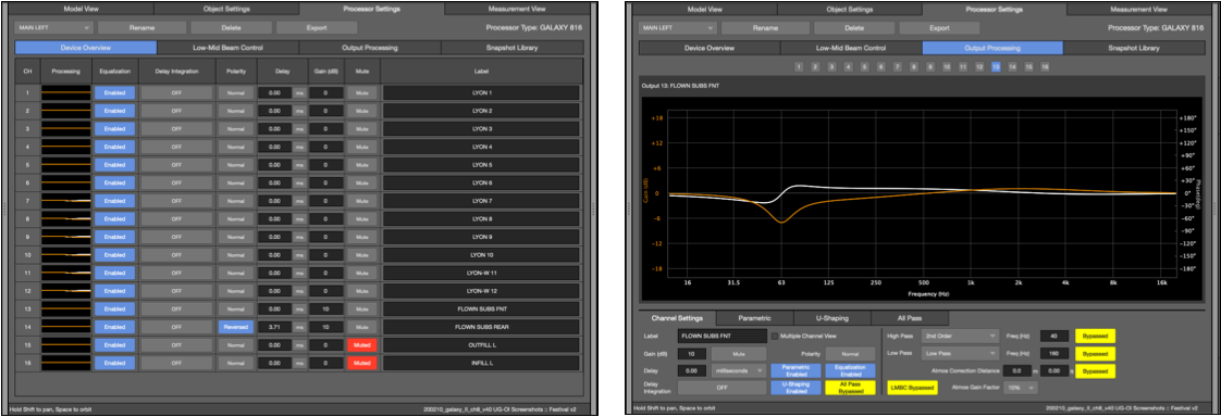
Processor Tab – All Processor Controls
Measurement View
The data for microphones inserted in the model is plotted in the Measurement View tab, including transfer functions, impulse response, 1/3 octave output levels, and maximum SPL.

Measurement View – Frequency & IFFT Response, Headroom
Additional Tabs
Cameras
Used in Model View, there are preset views and custom views that can be saved and recalled. Change the view from the drop-down in the upper left of the Model View tab ![]() or by selecting an option from the Viewport tab
or by selecting an option from the Viewport tab ![]() . The Viewport tab has four Viewport preset buttons and the Multiple Viewport toggle. The Create New camera view button opens the Camera Management window, where Cameras are managed, or TOOLS > CAMERA MANAGEMENT.
. The Viewport tab has four Viewport preset buttons and the Multiple Viewport toggle. The Create New camera view button opens the Camera Management window, where Cameras are managed, or TOOLS > CAMERA MANAGEMENT.
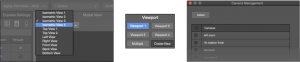
Camera Selection, Viewport Buttons, Camera Management Window
Inventory
Located on the left side of the application window ![]() , the Inventory tab provides an overview of all the objects in the project. Objects must be on an unlocked layer to modify them.
, the Inventory tab provides an overview of all the objects in the project. Objects must be on an unlocked layer to modify them.
- Click the icons at the top of the menu
 to minimize all but the selected type.
 - Select the
 icon for each object type to collapse or expand the list of individual object.
 - Click a listed object once to select the object in the model.
- Select, then press DELETE on the keyboard to delete.
- Double-click the name of an object and enter new text to rename.
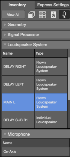
Inventory Tab
Express Settings
Express Settings are located on the left side of the application window ![]() . To display and edit basic settings, use the drop-down menu at the top to select different objects. To edit all object parameters, select the object in the model and switch to Object Settings tab
. To display and edit basic settings, use the drop-down menu at the top to select different objects. To edit all object parameters, select the object in the model and switch to Object Settings tab ![]() . For numeric entry, select value and enter new value or use up/down arrow keys to increase/decrease value. Objects must be on an unlocked layer to be modified.
. For numeric entry, select value and enter new value or use up/down arrow keys to increase/decrease value. Objects must be on an unlocked layer to be modified.
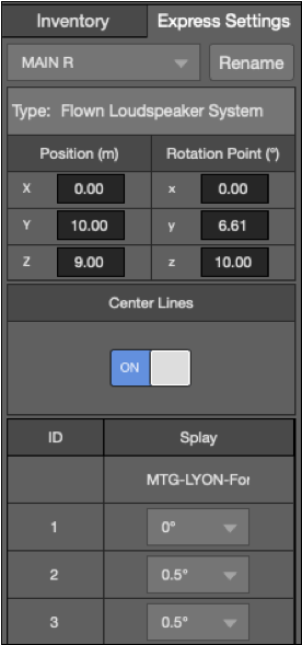
Express Settings Tab
Tools
Located on the top, right side of the application window ![]() , the Tools tab uses icons to represent a collection of actions and functions that can manipulate both the objects in the model and the appearance of the model. These tools apply to all entities that are visible in Model View: geometry, loudspeakers, and microphones.
, the Tools tab uses icons to represent a collection of actions and functions that can manipulate both the objects in the model and the appearance of the model. These tools apply to all entities that are visible in Model View: geometry, loudspeakers, and microphones.
Available Tools In Model Tab
Primitives
These icons represent the primitive shapes that can be added to the model and modified ![]() . Primitives are used to represent the geometry of the venue or are added to CAD drawings where pressure plots are desired. Primitive types include 3D shapes, 2D shapes, and a Free Draw option. The Free Draw tool is used to create polygons by entering coordinates or clicking in the Model View for each vertex.
. Primitives are used to represent the geometry of the venue or are added to CAD drawings where pressure plots are desired. Primitive types include 3D shapes, 2D shapes, and a Free Draw option. The Free Draw tool is used to create polygons by entering coordinates or clicking in the Model View for each vertex.

Available Primitives
Modifiers
Primitives can be manipulated in various ways by using modifiers ![]() . Extrude and Trim modifiers apply to only 2D Primitives. Offset modifies both 2D and 3D Primitives. Union, Intersect, and Subtract apply only to 3D Primitives. Objects must be on an unlocked layer to be modified.
. Extrude and Trim modifiers apply to only 2D Primitives. Offset modifies both 2D and 3D Primitives. Union, Intersect, and Subtract apply only to 3D Primitives. Objects must be on an unlocked layer to be modified.
Modifiers – 2D and 3D
Properties
When a Primitive is selected, its properties will be displayed in the Primitives tab ![]() . Different properties will be displayed depending on the geometry that is selected, but generally include position, orientation, and size. Objects must be on an unlocked layer to be modified.
. Different properties will be displayed depending on the geometry that is selected, but generally include position, orientation, and size. Objects must be on an unlocked layer to be modified.
Object Properties
Layers
All layers in the project are listed under this tab ![]() . Layers embedded in an imported DXF or SKP are also listed. Layers can be toggled between, locked/unlocked, made visible/hidden and renamed. Use the ADD and DELETE buttons to modify layers. It can be helpful to hide certain layers to work within a model. Use the Layer Management window to change layer colors, merge layers, and make bulk changes.
. Layers embedded in an imported DXF or SKP are also listed. Layers can be toggled between, locked/unlocked, made visible/hidden and renamed. Use the ADD and DELETE buttons to modify layers. It can be helpful to hide certain layers to work within a model. Use the Layer Management window to change layer colors, merge layers, and make bulk changes.
Layers Tab, Layer Management Window
Other Interface Features
Main Menu
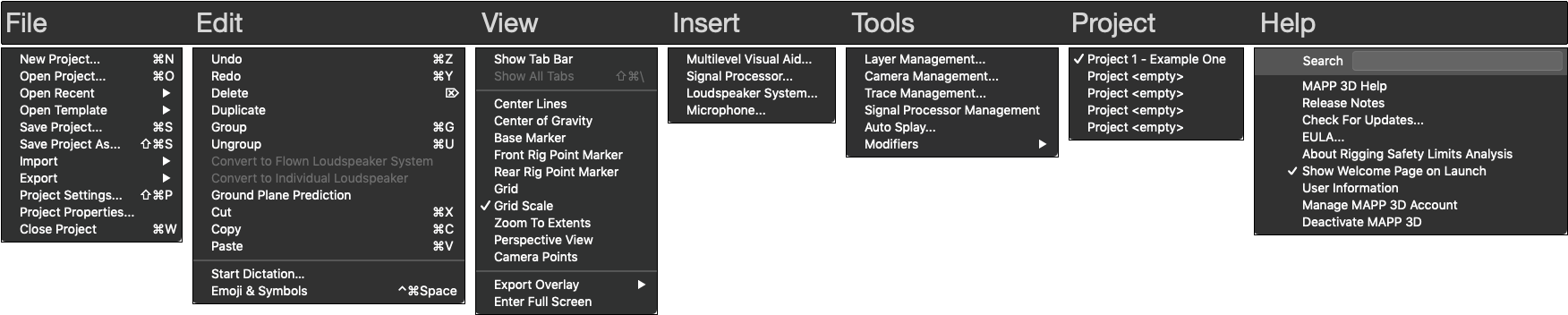
Main Menus – Used For Various Operations
Generate Documents
Use FILE > EXPORT to select documents to create.
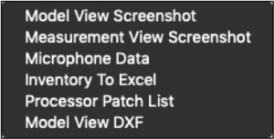
File > Export Sub Menu – Available Documents
Signal Processor Connection
TOOLS > SIGNAL PROCESSOR MANAGEMENT opens a window to manage processor connections. The processors used in the MAPP 3D Project can be connected to real or virtual Galileo GALAXY processors. The settings can be pushed either direction when connecting MAPP 3D to Galileo GALAXY processors. Control is bi-directional once settings are synchronized.
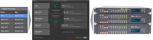
Inventory – Signal Processor Tab, Signal Processor Management Window, Galileo GALAXY Signal Processors
What’s Next?
Please see MAPP 3D Installation and Activation next.